Feel free. That was Mr. Selfs setup.Wow, horrifying 6dB in all that time. How about an oscillator driving a 10k load?
Yes, I have, but I am not waiting any surprises. Just the look in the data sheet tell us that the distortions may be at around -135dB region in the follower mode. The best performance you can get without a follower before the notch. If you really need the buffer in this place, then I can suggest to use the OPA1656 in the inverted mode.Very surprising! Do you have the OPA1656 at hand?
Quantify "much", not that I care at this point in time the difference of 10 or 15 years of process technology is like eons.
ROFL! Single figure of merit, single application, perfection has arrived!
EMI tea anyone?
Different devices certainly, different performance... Slightly, clear winner, sorry no bouquets!
I use the AD797 often, because it has very low and very simple distortion (only 2nd and 3rd as far as I can tell).
The circuits I use never have noise gains high enough for the distortion cap to make any difference, so you might not find the need to use one. I think you need to be running well above 20dB of noise gain for it to matter. Of course, you can try it out, but I've never seen any difference with noise gains less than 10dB.
FWIW, my experience with non-inverting stages (followers) has not been good - I cannot find one that can provide distortion below about -140dBc or thereabouts, whereas the same chip as an inverter can often do 10-15dB better. Driving 2kΩ or even 4kΩ is pretty easy for any competent amplifier, and the extra noise of an inverter is often not crippling.
Fully agree. Thanks for that tip on the '797, never knew that it is most effective at higher noise gains. God to know.
Jan
Idea for a precision composite for non-inverting mode :
- Looking at the inverting Groner/Polak composite, first add a precision high-speed buffer, to tap off the signal at the (+)-input -- which is at GND potential. So the buffer is a copy of GND.
- Connect the compensation return to that buffer, as well as the clamp ground, the slave amp (-)-input reference/fb network, and supply mid-point of an added floating supply for the master amp (slave amp remains on standard supply).
In inverting mode the buffered GND potential doesn't make a difference if the 'GND noise' is small and the output low impedance throughout.
Rearranging this building block to non-inverting we can see that the operation environment for the master stays exactly the same as in inverting mode, both input pin's voltages and output voltage are locked down at midpoint supply all the time. The difference is that the slave now excersizes its common-mode input range.
The buffer could be a (fast) composite as well, allowing its own master amp or input stage to run off the bootstrapped supply as well, for an absolute minimum amount of input parameter modulation.
The buffer and the floating rails shifter complicate things, though the shifter simplifies if we use the fact that the supply only needs to track the input voltage... which leaves enough headroom when the master amp runs on the lowest reasonable supply voltage.
First simulation have been very promising....
Last edited:
Douglas Self has already examined the AD797 in his book and the results were unconvincing. The LM4562 performs much better.
All I can go by is what I measure with my analyzer (APx-555) in my circuits (all inverting, low impedance, low noise gain). The differences I note are that some examples of the LM4562 can generate 4th and 5th harmonic, especially when the chip is allowed to heat up. Cool it with a thermal mass on top and the problem goes away. My unfounded theory is that the higher chip temperature tickles some sort of protection mechanism in the output stage, but regardless, I can repeat this undesirable behavior.
IMHO, bad forms of distortion are worse than a slight difference in distortion magnitude, so for my work, the LM4562 can be a worse choice if it is not thermally managed.
The basic distortion of both are so close to the 555 residual that it's dangerous to say that one is really better than another, but that's probably because I run these amps at low noise gain. Still, if I have a preference, the AD797 has slightly less distortion at low gains.
Compared to the AD797, the LM4562 has a nicer phase margin, so it's a lot easier to stick a buffer amp in the feedback loop. But, it's debatable whether this is needed for normal uses or not - both amps can cleanly drive 2kΩ, so unless really low impedance loads are expected, a buffer isn't interesting.
My other complaint about the AD797 is the expense. It's about $5-7 in moderate quantities, and it's a single, so it ends up being about 20x more pricey than an LM4562. This may not be important, but it is a factor for me.
Still, for my tests, the AD797 is the amp that generates distortion measurements that look most like the analyzer residual alone, so I've been using it as a test fixture amp to test other aspects of my circuits. As always, YMMV.
Idea for a precision composite for non-inverting mode :
- Looking at the inverting Groner/Polak composite, first add a precision high-speed buffer, to tap off the signal at the (+)-input -- which is at GND potential. So the buffer is a copy of GND.
- Connect the compensation return to that buffer, as well as the clamp ground, the slave amp (-)-input reference/fb network, and supply mid-point of an added floating supply for the master amp (slave amp remains on standard supply).
In inverting mode the buffered GND potential doesn't make a difference if the 'GND noise' is small and the output low impedance throughout.
Rearranging this building block to non-inverting we can see that the operation environment for the master stays exactly the same as in inverting mode, both input pin's voltages and output voltage are locked down at midpoint supply all the time. The difference is that the slave now excersizes its common-mode input range.
The buffer could be a (fast) composite as well, allowing its own master amp or input stage to run off the bootstrapped supply as well, for an absolute minimum amount of input parameter modulation.
The buffer and the floating rails shifter complicate things, though the shifter simplifies if we use the fact that the supply only needs to track the input voltage... which leaves enough headroom when the master amp runs on the lowest reasonable supply voltage.
First simulation have been very promising....
Schematic?
Jan
I was looking at the Vishay Zfoil resistors:
https://www.mouser.be/datasheet/2/428/zseries-1022194.pdf
Jan
Ok, those are better than s102k. They are pricey, of course.
Let me know if you are interested in the used market.
Randall
Ok, those are better than s102k. They are pricey, of course.
Let me know if you are interested in the used market.
Randall
What used market?
Jan
If I properly understand, we are talking about the opamp after the notch? The signal level after the notch is little higher than 2mV in this case (if the 40dB amplification gets app -18dB when the 0dBFS is 2V). So, the opamp input capacitance changes must be negligible.
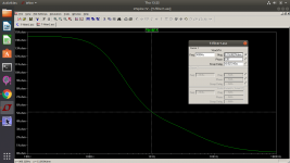
The changes are most certainly negligible but so is -120 dB distortion. Look at the output impedance of the passive notch and use that as the source Z for testing the different opamps. I'm attaching a quick sim I tried which shows around a 10K source.
Attachments
Jan- I'm not sure where you will find caps as stable over temperature as those Vishay Z-Foil resistors. Polystyrene are -150 ppm/degree C and even NPO are +/-30 ppm. Chasing 1 PPM will be hard to extract with the cap tolerances. if you were chasing a (really) small change some varactor diodes could get you there assuming the distortion they add will be very small which it won't be.
")
Hah! I have developed a small oven-like construction with heating and a control loop keeping those caps (there are 4) at 0.001C stable short-time, during a measurement cycle!
There is of course a difference between accuracy and stability. You can cal-out accuracy but for extremely precise measurements stability is paramount over the measurement cycle. Over a longer time it will drift some, for instance the sensor for the temp control drifts 0.08C over 10 years.
Jan
There is of course a difference between accuracy and stability. You can cal-out accuracy but for extremely precise measurements stability is paramount over the measurement cycle. Over a longer time it will drift some, for instance the sensor for the temp control drifts 0.08C over 10 years.
Jan
Last edited:
Thinking about the best and most transparent high-input impedance buffer for extremely low distortion I would use a non-inverting buffer with bootstrapped power supplies feeding into an inverting Groner/Polak opamp. ...
This is a great idea, but I think the bulk of the improvement would be gained from the bootstrapped supplies, which would greatly reduce all manner of common mode distortions. However, I'm not sure what the composite after that buys you.
Time to revisit bootstrapped supply schemes!
Monte you are right, for the buffer the composite is not required. I was mixing it up with a buffered post-notch gain stage.
Doug Self has done a lot of measurements with several supply bootstrap schemes that all show improvements to some extend. Some are as simple as a couple of resistors, others involve aux opamps and level shifters. Good read.
Jan
Doug Self has done a lot of measurements with several supply bootstrap schemes that all show improvements to some extend. Some are as simple as a couple of resistors, others involve aux opamps and level shifters. Good read.
Jan
The changes are most certainly negligible but so is -120 dB distortion. Look at the output impedance of the passive notch and use that as the source Z for testing the different opamps. I'm attaching a quick sim I tried which shows around a 10K source.
This is the output impedance of Viktor's 1k passive notch filter (source imp = 50R)
Attachments
Last edited:
This is the output impedance of Viktor's 1k passive notch filter (source imp = 50R)
The output z should go to almost zero to have lowest thd in the next op amp stage, but the notch filter is as it is. Maybe an active notch filter, but according to Victor that introduces new thd into the chain.
You can build a low z notch filter with 100nF MKP caps, but in that case you need an input buffer. More thd from caps, more thd from the buffer.
Last edited:
Today I did some simulations. Having no input buffer is not so bad when you use e.g. the notch from Victor. The measurement error is with H0=1kHz
Zout src = 600: H1-H10: -0.7 dB .. -2.5 dB
Zout src = 200: H1-H10: -0.2 dB .. -1 dB
Zout src = 100: H1-H10: -0.1 dB .. -0.5 dB
Zout src = 50: H1-H10: -0 dB .. -0.2 dB
You can live with that. You must be careful to have a DUT that doesn't have a large output impedance, e.g. 1k ..10K.
Zout src = 600: H1-H10: -0.7 dB .. -2.5 dB
Zout src = 200: H1-H10: -0.2 dB .. -1 dB
Zout src = 100: H1-H10: -0.1 dB .. -0.5 dB
Zout src = 50: H1-H10: -0 dB .. -0.2 dB
You can live with that. You must be careful to have a DUT that doesn't have a large output impedance, e.g. 1k ..10K.
Last edited:
- Home
- Design & Build
- Equipment & Tools
- Low-distortion Audio-range Oscillator