I have assembled the sine generator and there are problems with the signal spectrum. What for excitation of a sine curve?
My FFTs look very similar to that one when the LME49720 is receiving DECT cordless phone EMI. I have an earlier post on this.
I have a trick for using an LM339 as an active precision rectifier. It has an open collector output and is a linear device inside that recovers from overload really fast so it works well for this. Its "negative logic" so you need to think negative peak capture. You get 4 in a package so its a good match for this. Attached is an illustration of the concept.
I've used the LM339 as peak detectors taking advantage of the "wired OR" open-collector outputs and its workable. Other comparators may not be "op amp-like" enough to work.
Anyone else notice the 170 dB open loop gain composite op amp* he made with 4580s and complimentary input transistors in this link? Oscillator
(* from the translation.)
An externally hosted image should be here but it was not working when we last tested it.
I would like to try this with Victor's oscillator.
Last edited:
My FFTs look very similar to that one when the LME49720 is receiving DECT cordless phone EMI. I have an earlier post on this.
You are right, it does look like the spectrum of a DECT interference. In this case it would be a base station with no connection. If there was a connection, it would be dominated by 100 Hz and harmonics instead of 10 Hz (I assume that there is also a peak at 10 Hz, but it is a bit difficult to see).
On the other hand there seems to be a slight offset from the 20, 30 etc. Hz. A DECT signal should normally have a very accurate timing within 5 ppm.
It could perhaps also be a beacon from a Wi-Fi router.
Found that post. I think the LME49720's EMI susceptibility is tuned to DECT. My test circuit is within 3-4 feet of a WiFi access point, about 8-10 feet from an idle 4G phone and about 8 feet from the DECT base shown below in idle state. Powering down the DECT base removes the interference completely. Its almost as if the LME49720s ESD diodes are peaked at DECT frequencies.
This is an FFT comparison of an LME49720 and OPA1612. The output of the notch filter has 40 dB gain. The oscillator output level is approximately +6 dBu. The OPA1612's 2nd and 3rd THD is in the range of -135 to -140 dBc.
My cell phone was on the other side of the room but a WiFi access point was about 3' from the prototype which has a bottom metal shield and a grounded top foil shield sandwiched between cardboard. Other than the 60 Hz and related components in the OPA1612 example there is not much benefit to the shield with that op amp. The LME49720 benefits greatly from the shield but not enough.

LME49720 FFT of oscillator output after notch filter. +40 dB gain.

OPA1612 FFT of oscillator output after notch filter. +40 dB gain.
The bursts seem to begin around 20 Hz and at first appear line-related. Triggering the 'scope from the 60 Hz powerlinline shows that the burst noise is asynchronous to the line frequency.
The NE5523, NJM2114, NJM2068, NJM2043, OPA2134, OPA2604, OPA1642 and MC33078 will all run in that circuit with various THD signatures higher than the OPA1612 but otherwise they look clean.
The LME49720 has lots of spurs.
Dimitri I'm not sure those links are to the RF problems. You might have had something different in your clipboard when you pasted them.
It could perhaps also be a beacon from a Wi-Fi router.
Yes it is Wi-Fi router . Metal shield, removes this problem.
Strangely, the other exactly such generators work perfectly without a shield.
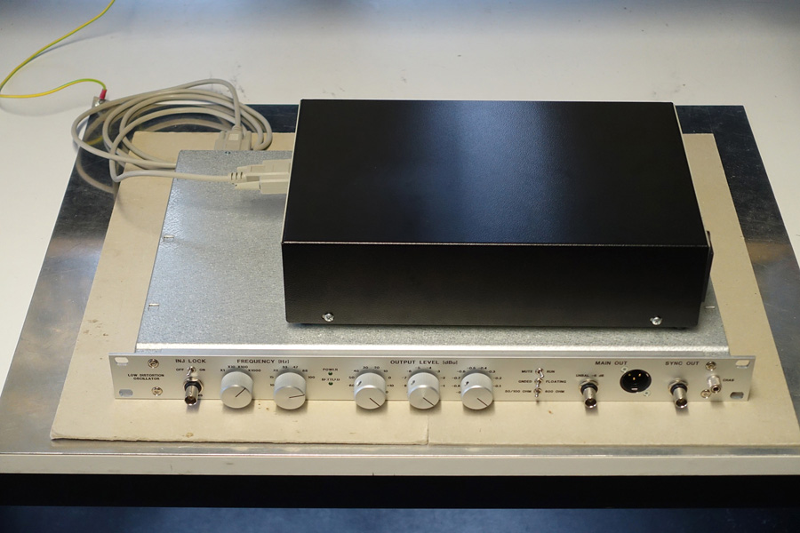
Several weeks ago the external PSU for my low distortion oscillator finally got finished:
Difficulties sourcing a suitable power transformer (it requires extra shielding) delayed the process.
I'm now working on the detailed performance evaluation. So far things look promising.
Samuel
An externally hosted image should be here but it was not working when we last tested it.
Difficulties sourcing a suitable power transformer (it requires extra shielding) delayed the process.
I'm now working on the detailed performance evaluation. So far things look promising.
Samuel
What kind of shielding do you use on the transformer?
I was shopping for a transformer with independent electrostatic shields for both the primary and secondary side. To provide a floating oscillator output the power supply can be floated. Common-mode currents from the transformer cause interference in this mode and must thus be very low.
Is that an aluminum front panel on a galvanized steel case for the actual oscillator?
Yes; IIRC a standard product from Schroff.
Samuel
High isolation transformers are rare and difficult. The best results I have had used a very large core running at low flux with the primary and secondarys on separate legs. A shield on each winding. Even with the shields you cave capacitance between the shields so finding the best places for them becomes important. Also the windings will couple capacitive currents into the shields to those currents need to be managed. There are no simple solutions. Knowing your transformer specialist helps a lot. Mine retired almost 20 years ago and I have not found anyone as sharp yet. But I'm still looking.
Hi Demian
My guy also retired many years ago from Triad. Triad has a product line MD-250 through MD-3000 that is medical isolation and has verily low leakage. The MD-250U is about $125.00 from Digikey. I use mine for debug of switching PS products it is about 14ua of leakage.
Duke.
My guy also retired many years ago from Triad. Triad has a product line MD-250 through MD-3000 that is medical isolation and has verily low leakage. The MD-250U is about $125.00 from Digikey. I use mine for debug of switching PS products it is about 14ua of leakage.
Duke.
A bit about metal cases. The one Samuel showed has a front panel of aluminum. The most common alloy is 6061 which is a good general purpose choice. For sheet metal cases it is often 5052 which is a bit cheaper as it does not need to be as easily weldable. It looks like the panel has been clear anodized which puts a hard nonconductive coating on the metal. As this is a commercial case the holes would have been made after the anodizing process and the edges would be exposed and conductive.
The case body itself is made of a steel called galvanneal or similar. This is a mild steel of typically 30,000 lbs yield strength that has been galvanized. As that process can leave a non-uniform temper in the metal, it is annealed after that to make sure the temper and yield strength are uniform. The yield strength is very important in bending the metal. After a bend there is spring back of the bend angle. It is typical to bend a few degrees more than the typical 90 degrees so that with spring back the final angle is 90 degrees. So if the yield strength varies due to galvanizing the bends will not all be the same. If it varies sheet to sheet you cannot adjust the bending machinery to get good results. So folks who bend cases use steel where the yield strength has a tolerance of typically 5%. Fussy folks who buy steel by the roll scrap the first and last two turns as that is where the most variance is found.
Now this brings up two issues. The first is where bare aluminum touches galvanized steel in the presence of moisture corrosion will take place. There also will be a small and irregular voltage generated from the corrosion process. After all you really have made a 1.54 volt battery.
The second issue is the hysteresis in steel. Running an alternating current in a conductor near a steel surface will induce a magnetic field and because of the hysteresis introduce distortion into that field. Now how close and how much distortion depends on the current level and the impedance of the circuitry.
The last folks I saw run into those problems went to an all copper case. I ended up redoing their project and found all aluminum worked well for the final gizmo.
and don't place your output inductor/s right next to the steel panels.
Found out the hard way did you?
Hi David
By placing Alum or Copper between the COIL and the STEEL will reduce the field strength from getting into the steel. The coil will now look more like air coil in space. This is what I did with the Audio Precision AUX0025 to keep the Air Core Inductors in a linear mode as the covers were steel. The alum strips were double sticky tape on top & bottom covers.
Duke
A bit about metal cases. <snip>
This sounds like we should use the john curl method of using a solid block of aluminum.
Hi David
By placing Alum or Copper between the COIL and the STEEL will reduce the field strength from getting into the steel. The coil will now look more like air coil in space. This is what I did with the Audio Precision AUX0025 to keep the Air Core Inductors in a linear mode as the covers were steel. The alum strips were double sticky tape on top & bottom covers.
Duke
Double sided tape.
I'm assuming a thin layer of aluminum is effective then.
- Home
- Design & Build
- Equipment & Tools
- Low-distortion Audio-range Oscillator