A couple of slave op amps can be used to...
My initial, too-quick skim of the Tektronix discussion left me confused whether they had used this idea, so I did think about it.
The extra complexity and power draw doesn't seem worth it for my application.
I would like to have battery operation as an option, both for portability and to make it easy to isolate and float, so power matters.
Also the scheme would require to switch the capacitors accurately simultaneously.
I expect that simple rotary switches are subject to substantial tolerances, so probably relays would be required, with even more power draw.
Does that make sense?
Best wishes
David
Dave Unless you want the oscillator to be portable you can run just the oscillator core off batteries and the rest off a well regulated power supply.
My oscillator really doesn't show much power supply junk of itself running off a cheap bench supply. The noise gets in from outside EM sources. Switching circuits like my cable modems do the most damage. I moved the modem to the basement. I've had days when the Ac power EM has been so low nothing shows up in the measurement. I found my old Sansui amp was oscillating at some 60MHz because this showed up in measurement. Drives the EMU0204 nuts. The oscillator powering is the least of your problems.
But beware...ripple...
Well, yes, that's exactly why I wrote
"The quadrature outputs would have to be accurately matched".
I assumed that the quadrature outputs would be matched when the RC time constants matched.
Sorry if this was not clear.
Best wishes
David
...one way I like to think of it is that the level of the agc feedback signal off of the first integrator may become mismatched with the level of the signal from the other integrator that feeds the agc rectifier...
I had not previously considered it that way, it's quite helpful so, as always, thanks.
I am now reasonably confident that the SVO does indeed have a lower sensitivity to frequency RC mismatch than a Wien.
That is probably old news but I haven't seen it explicitly stated.
Not a surprise, in physical terms the Q of the Wien is much lower.
So my idea for a swept SVO still looks reasonable.
Best wishes
David
You could make a voltage-swept SVO using current-output DACs between the integrators, or multipliers in front of the integrator resistors. Of course, noise and distortion must be considered. You could also use a THAT stereo dual audio VCA. It would have the advantage of providing a logarithmic sweep vs control voltage. Again, in any of these approaches, distortion, noise and residual dc output as a function of sweep voltage must be considered. The latter could introduce agc disturbances with frequency change.
Cheers,
Bob
You could [use] current-output DACs...or multipliers...
AP used MDACs...
Thanks but I have much simpler plans, I need a project I can finish in a human lifetime.
Distortion measurements of amplifiers and similar electronics requires very low THD + N but only at comparatively few fixed frequencies.
Whereas an all-purpose swept oscillator really needs amplitude stability, not like my atrocious old thermistor Wien.
So the plan is for switched frequencies 1,2,5,10,20,50... that can be calibrated and optimized, and a selectable control to sweep from each base frequency.
That's about the same level of complexity as Bob's oscillator, the extra parts for the sweep option balanced by fewer frequencies per decade.
That also means I can afford to trim each frequency individually where Bob trimmed each decade.
I won't have a distortion analyser so the switches can be much simpler, maybe have accessible status lines to make it easier to do a relay controlled analyser as a modular add-on later, or link to a distortion multiplier and computer based measurement, best of all worlds?
Best wishes
David
I just realized I have re-invented the Tektronix TM500 series Audio Analyser in that last sentence.
Last edited:
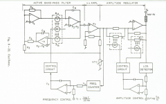
Radiometer BKF-10
This venerable instrument had a voltage tunable state variable oscillator that went from 20 Hz to 20 KHz in a single sweep. It was around .005% THD.
I have the full service manual. This was the only page I was up for scanning tonight. If there is interest I'll try to scan the actual circuits in the next few days. The instrument is a real monument to skilled analog design with both the oscillator and the analyzer fully analog, including log displays on the nice large analog meters and the analyzer auto-tunes across the whole range. The target was tape recorder testing so they had to operate independently. I had one that needed some attention but lost track of it.
Attachments
And now for something new: Ultra Low Distortion 0 00006 THD Generator Audio Analyzer DIY Audio | eBay
Anyone have experience? They claim around -126 dB THD. The price is reasonable. I just bought the last one. https://www.rexotech.com/home/downloads/finish/1-documents/15-manual-rexotech-uld4-v1-02.html
Anyone have experience? They claim around -126 dB THD. The price is reasonable. I just bought the last one. https://www.rexotech.com/home/downloads/finish/1-documents/15-manual-rexotech-uld4-v1-02.html
(...) or multipliers in front of the integrator resistors. Of course, noise and distortion must be considered.
I've tried this approach using a pair of AD633 - it works very well, but noise performances are relatively poor, and THD not quite very low (but it is indeed lower than the THD of a typical VCO).
L.
And now for something new: Ultra Low Distortion 0 00006 THD Generator Audio Analyzer DIY Audio | eBay
Anyone have experience? They claim around -126 dB THD. The price is reasonable. I just bought the last one. https://www.rexotech.com/home/downloads/finish/1-documents/15-manual-rexotech-uld4-v1-02.html
Amplitude settling time 1-6 MINUTES??!!
Cheers,
Bob
That unit showed in my eBay notifications this week as well. I expect a full report once you receive it. Beyond the settling time, did you see in the instructions where you should not have anything connected to the output connectors when turning on or off? Report back...I do like the fact it is already in an enclosure.
... time 1-6 MINUTES??!!
Hi Bob
Presumably that's mainly to let it warm up, doesn't bode well for temperature stability.
But it does remind me that some oscillators are slow to start.
Previously in this thread it was noted that Bruce Hofer's Tektronix 505 oscillator had the unused frequency capacitors in the two integrators at different potentials to allow it to be prepared and thus settle faster after a decade switch.
Seems to me this could also be done to allow the oscillator to start essentially instantly.
It's a State Variable oscillator so we have access to all the state variables.
We can put it directly in the state we want, that of stable oscillation.
At least, that's my physical intuition, any comments?
@COLUKE
Hi Luca
I read some of your earlier comments about the slow start of one of your test oscillators.
Nice to see you rejoin this thread just as the subject comes back.
Did you just live with the delay or did later versions fix it?
Best wishes
David
Hi BobSeems to me this could also be done to allow the oscillator to start essentially instantly. It's a State Variable oscillator so we have access to all the state variables. We can put it directly in the state we want, that of stable oscillation.
See e.g. US-patent 5714911; also the reference linked in http://www.diyaudio.com/forums/equipment-tools/205304-low-distortion-audio-range-oscillator-439.html#post4666430 uses exactly this idea for leveling.
Oscillators are an extremely well researched topic. It's hard to come up with anything fundamentally new...
Samuel
Hi Bob
Presumably that's mainly to let it warm up, doesn't bode well for temperature stability.
But it does remind me that some oscillators are slow to start.
Previously in this thread it was noted that Bruce Hofer's Tektronix 505 oscillator had the unused frequency capacitors in the two integrators at different potentials to allow it to be prepared and thus settle faster after a decade switch.
Seems to me this could also be done to allow the oscillator to start essentially instantly.
It's a State Variable oscillator so we have access to all the state variables.
We can put it directly in the state we want, that of stable oscillation.
At least, that's my physical intuition, any comments?
@COLUKE
Hi Luca
I read some of your earlier comments about the slow start of one of your test oscillators.
Nice to see you rejoin this thread just as the subject comes back.
Did you just live with the delay or did later versions fix it?
Best wishes
David
Hi Dave,
Actually, this idea brings back old memories from my Bell Labs days. This is akin to a very old idea called shock excitation. It was used in the oscillators of Touch-Tone telephones to initiate immediate start-up. A small current of the appropriate value was run through the tuning inductors and was interrupted when the button was pressed.
BTW, this ingenious oscillator used only a single transistor to produce both of the Touch-Tone frequencies. Transistors were expensive back then. The single transistor amplifier at the heart of the oscillator was forced to operate in its linear region.
Cheers,
Bob
also the reference linked in http://www.diyaudio.com/forums/equipment-tools/205304-low-distortion-audio-range-oscillator-439.html#post4666430 uses exactly this idea
You must have a different number of posts per screen to me because this doesn't link to a post with a reference, can you tell me the post number?
Oscillators are an extremely well researched topic...
Yes, I don't expect to have invented new ideas.
I mention my ideas so that I have the benefit of the collective experience to help me find more information.
I don't want to reinvent more of the wheel than necessary.
")
Best wishes
David
Patent 5714911 by Barrie Gilbert. I'm quite flattered that I reinvented an idea from such a smart person
Last edited:
.. This is akin to a very old idea called shock excitation. It was used in the oscillators of Touch-Tone telephones to initiate immediate start-up. A small current....and was interrupted when the button was pressed.
Yes, same idea except in this case it would be a potential on a capacitor and not a current in an inductor.
I don't think I have actually seen it used, maybe a minor improvement in usability but it's no cost so I like it.
Mostly I wanted to check if my feel for state variables was accurate.
Also, if we can start the oscillator at the correct amplitude and switch it with minimal disturbance then perhaps we can eliminate the need for non-linear elements to handle severe transients in the leveler loop.
Not just to save a few components but mainly to make it easier to understand.
Best wishes
David
Last edited:
- Home
- Design & Build
- Equipment & Tools
- Low-distortion Audio-range Oscillator