Oops that pic was at the Jfet gate.
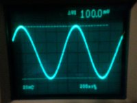
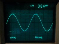
Here are pics of the drain and op amp input.
The gain at peak resonance in a bridged T is no where near that of an SVO.
This accounts for the higher input level in the Bridged T oscillator.
Here are pics of the drain and op amp input.
The gain at peak resonance in a bridged T is no where near that of an SVO.
This accounts for the higher input level in the Bridged T oscillator.
Attachments
HP339a Knobs
Here Y'all,
I've tried to do a couple of things for the knobs.
I've come up with my "final solution" (fs).
It works well and circumcises the HP knobs in their tracks.
It's not fancy,
It's not elegant,
It's not very pretty,
It just plane works.
It's not obvious and took me
a month of trying to figure out
how to make it come out right.
Then, there is "them" the other knobs.
Film at 11.
Cheers,
Sync
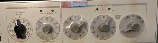
HP 339A Knob Mods
Here y'all go.
I beat my goal at 11 by 15 minutes.")
This unit never had a Distortion knob.
Just putting a knob on the unit got to be a
real PITA. It works just the opposite as you
think it does. I got tired of thinking about it
and spent a month working on it.
The kid ran off with my compass
so I had to hand trim it.
The fs is on the left. Other iterations
are shown trying to keep an original
look.
To read the knobs without finding my
magnifiers for my old eyes I made the
covers for the skirts shown on the right
four knobs.
Eventually I made a ring that just slips
on to the skirt and sticks. If you get it
wrong your screwed. Along the way
you can see where I slit the ring.
I came up with that idea after I stripped
out the set screw trying to loosen it.
I toyed with the idea of making them available
to other folks but even getting the things off
a sheet is a lot more tedious that I ever would have
thought. These aren't decals, decals don't last.
This is probably simple with Illustrator, but
I can't afford it and don't want to spend a long
time trying to figure it out again.
Here y'all go.
I beat my goal at 11 by 15 minutes.
This unit never had a Distortion knob.
Just putting a knob on the unit got to be a
real PITA. It works just the opposite as you
think it does. I got tired of thinking about it
and spent a month working on it.
The kid ran off with my compass
so I had to hand trim it.
The fs is on the left. Other iterations
are shown trying to keep an original
look.
To read the knobs without finding my
magnifiers for my old eyes I made the
covers for the skirts shown on the right
four knobs.
Eventually I made a ring that just slips
on to the skirt and sticks. If you get it
wrong your screwed. Along the way
you can see where I slit the ring.
I came up with that idea after I stripped
out the set screw trying to loosen it.
I toyed with the idea of making them available
to other folks but even getting the things off
a sheet is a lot more tedious that I ever would have
thought. These aren't decals, decals don't last.
This is probably simple with Illustrator, but
I can't afford it and don't want to spend a long
time trying to figure it out again.
Attachments
Last edited:
Here y'all go.
I beat my goal at 11 by 15 minutes.
This unit never had a Distortion knob.
Just putting a knob on the unit got to be a
real PITA. It works just the opposite as you
think it does. I got tired of thinking about it
and spent a month working on it.
The kid ran off with my compass
so I had to hand trim it.
The fs is on the left. Other iterations
are shown trying to keep an original
look.
To read the knobs without finding my
magnifiers for my old eyes I made the
covers for the skirts shown on the right
four knobs.
Eventually I made a ring that just slips
on to the skirt and sticks. If you get it
wrong your screwed. Along the way
you can see where I slit the ring.
I came up with that idea after I stripped
out the set screw trying to loosen it.
I toyed with the idea of making them available
to other folks but even getting the things off
a sheet is a lot more tedious that I ever would have
thought. These aren't decals, decals don't last.
This is probably simple with Illustrator, but
I can't afford it and don't want to spend a long
time trying to figure it out again.
A chicken head?
Great Idea though.
I have some decal sheets. One puts them through a laser printer.
Soak it in water and transfer to a surface. Just like the old airplane models.
Last edited:
A brief update on the progress of my project: the PCB is fully assembled, and the oscillator up and running. I can present a few preliminary THD+N measurements done with the SYS-2722 analyzer. First of all THD+N versus frequency at three different measurement bandwidths and with +22 dBu output level (a "sweet spot" of the analyzer):
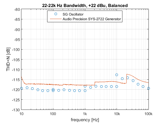

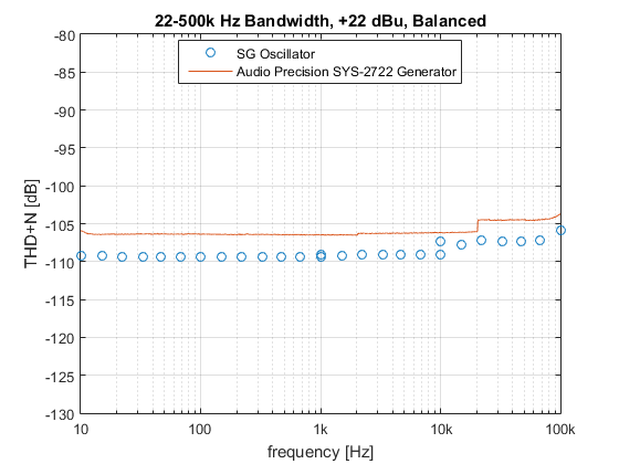
At frequencies below 10 kHz, the measurement is mostly dominated by the analyzer noise floor. The true THD+N residual of the oscillator is probably several dBs lower. At frequencies of 10 kHz and 15 kHz in the highest frequency range (10-100 kHz), my oscillator has higher THD+N than the generator of the SYS-2722; that is because the frequency range switching is done at 10 kHz instead of 20 kHz. I accepted this compromise for easier frequency control, and because THD+N measurements under these conditions are not particularly meaningful anyway (essentially all harmonics removed by the 22 kHz filter).
Now THD+N versus level, at two frequencies/measurement bandwidths:
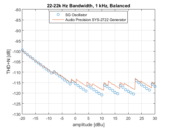
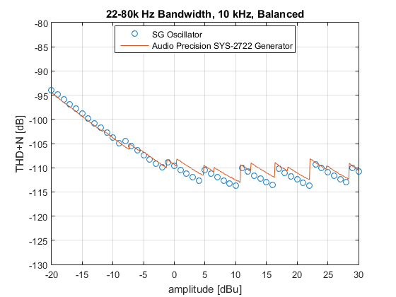
Again performance appears to be dominated by the analyzer; its 6 dB gain ranging steps are clearly visible, while those of the oscillator (at -10 dBu, 0 dBu, +10 dBu etc.) are not detectable.
Some work remains to be done for the output driver stage, where there is a bit of excess distortion at 100 kHz. I have located the source, but not yet found a complete solution.
Samuel
At frequencies below 10 kHz, the measurement is mostly dominated by the analyzer noise floor. The true THD+N residual of the oscillator is probably several dBs lower. At frequencies of 10 kHz and 15 kHz in the highest frequency range (10-100 kHz), my oscillator has higher THD+N than the generator of the SYS-2722; that is because the frequency range switching is done at 10 kHz instead of 20 kHz. I accepted this compromise for easier frequency control, and because THD+N measurements under these conditions are not particularly meaningful anyway (essentially all harmonics removed by the 22 kHz filter).
Now THD+N versus level, at two frequencies/measurement bandwidths:
Again performance appears to be dominated by the analyzer; its 6 dB gain ranging steps are clearly visible, while those of the oscillator (at -10 dBu, 0 dBu, +10 dBu etc.) are not detectable.
Some work remains to be done for the output driver stage, where there is a bit of excess distortion at 100 kHz. I have located the source, but not yet found a complete solution.
Samuel
Last edited:

A brief update on the progress of my project: the PCB is fully assembled, and the oscillator up and running. I can present a few preliminary THD+N measurements done with the SYS-2722 analyzer. First of all THD+N versus frequency at three different measurement bandwidths and with +22 dBu output level (a "sweet spot" of the analyzer):
At frequencies below 10 kHz, the measurement is mostly dominated by the analyzer noise floor. The true THD+N residual of the oscillator is probably several dBs lower. At frequencies of 10 kHz and 15 kHz in the highest frequency range (10-100 kHz), my oscillator has higher THD+N than the generator of the SYS-2722; that is because the frequency range switching is done at 10 kHz instead of 20 kHz. I accepted this compromise for easier frequency control, and because THD+N measurements under these conditions are not particularly meaningful anyway (essentially all harmonics removed by the 22 kHz filter).
Now THD+N versus level, at two frequencies/measurement bandwidths:
Again performance appears to be dominated by the analyzer; its 6 dB gain ranging steps are clearly visible, while those of the oscillator (at -10 dBu, 0 dBu, +10 dBu etc.) are not detectable.
Some work remains to be done for the output driver stage, where there is a bit of excess distortion at 100 kHz. I have located the source, but not yet found a complete solution.
Samuel
Hi Samuel,
Amazing work! Do you have any plan to test it with latest APX555 in the near future?
BR
Paul
A brief update on the progress of my project: the PCB is fully assembled, and the oscillator up and running. I can present a few preliminary THD+N measurements done with the SYS-2722 analyzer. First of all THD+N versus frequency at three different measurement bandwidths and with +22 dBu output level (a "sweet spot" of the analyzer):
At frequencies below 10 kHz, the measurement is mostly dominated by the analyzer noise floor. The true THD+N residual of the oscillator is probably several dBs lower. At frequencies of 10 kHz and 15 kHz in the highest frequency range (10-100 kHz), my oscillator has higher THD+N than the generator of the SYS-2722; that is because the frequency range switching is done at 10 kHz instead of 20 kHz. I accepted this compromise for easier frequency control, and because THD+N measurements under these conditions are not particularly meaningful anyway (essentially all harmonics removed by the 22 kHz filter).
Now THD+N versus level, at two frequencies/measurement bandwidths:
Again performance appears to be dominated by the analyzer; its 6 dB gain ranging steps are clearly visible, while those of the oscillator (at -10 dBu, 0 dBu, +10 dBu etc.) are not detectable.
Some work remains to be done for the output driver stage, where there is a bit of excess distortion at 100 kHz. I have located the source, but not yet found a complete solution.
Samuel
Hi Samuel,
These are really great results! Thanks for all your hard work and research on this topic.
Cheers,
Bob
Thanks again for all the interest! Yesterday I've found a near-complete solution for the mentioned issue with the output driver.
But I've got the chance to evaluate one several month back, and I've used this opportunity to compare the Tektronix SG 505 with the Audio Precision System One, SYS-2722 and APx555 generators (unfortunately my own design wasn't ready at the time). This week I finally got around to compiling the measurement data; here we go: low_distortion_oscillator_comparison.pdf (big file!).
Samuel
Unfortunately I don't have regular access to one.Do you have any plan to test it with latest APx555 in the near future?
But I've got the chance to evaluate one several month back, and I've used this opportunity to compare the Tektronix SG 505 with the Audio Precision System One, SYS-2722 and APx555 generators (unfortunately my own design wasn't ready at the time). This week I finally got around to compiling the measurement data; here we go: low_distortion_oscillator_comparison.pdf (big file!).
Samuel
I would have liked to see Victor's single frequency oscillator in the comparison since it's an available cost effective source in this tier of distortion.
There are legitimate questions about the numbers and harmonic cancellations however even so they represent distortion levels low enough to test pretty much anything .
Sent from my SGH-M919 using Tapatalk
There are legitimate questions about the numbers and harmonic cancellations however even so they represent distortion levels low enough to test pretty much anything .
Sent from my SGH-M919 using Tapatalk
Some theory?
Just pulled out my old Wien B. oscillator out to check out a speaker.
It's a DIY antique (classic?) with the now unobtainable miniature vacuum thermistor amplitude stabilization.
So, of course, the output bounces atrociously as I try to sweep the frequency.
It would be nice to have a low distortion sweep oscillator without this problem, even if the distortion can't match a fixed frequency step unit.
The bounce is a classic under-damped feedback loop but a quick check has turned up remarkably little analysis of the theory, as applied in this case.
I expect I can work out why the Wien B. is so sensitive to mismatch of the components that set frequency (potentiometer tracks in this case) but surely it's been done?
In fact I am surprised that I haven't found much detailed analysis of different oscillator types, beyond the Bruce Hofer convention paper that recommends State Variable.
Reputable companies like HP seem to have picked almost arbitrarily between Wien, Tee, some Phase Shift and I even found a Sallen-Key version.
Twin Tee needs a few extra components so the lack of popularity is explicable but it's widely used in distortion analysers.
Intuitively I expect it's sharper notch would improve stability in oscillators too.
So does anyone know a useful reference that ties all this up?
Or perhaps the subsequent dominance of State Variable implementations means all I need is the Hofer paper.
Does anyone have a link? I believe the AES permits this, since it didn't appear in the Journal.
David Zan
Last edited:
You can't find much because there isn't much written up on oscillators at least not in English.
I have continuously tuned state variable of my own design with fast settling.
It's 16 bit Mdac tuned and controlled by a PC app. It outputs a very low distortion 2.5Vrms source.
Mr Marsh had it for a while to test out. Maybe he can comment on it for you.
The HP339a/239A is a bridged T oscillator.
I have continuously tuned state variable of my own design with fast settling.
It's 16 bit Mdac tuned and controlled by a PC app. It outputs a very low distortion 2.5Vrms source.
Mr Marsh had it for a while to test out. Maybe he can comment on it for you.
The HP339a/239A is a bridged T oscillator.
I did test it and I had to do a lot of extensive shielding and best grounding, isolation transformer, filtered ac power etc etc to read the distortion. I am sure I gave the test results some where. It is extremely low distortion also. What I like and asked for, if it was possible to develope, was a continuously variable freq gen - which David's is. It helps with null finding and tuning to get best results possible. This is unique in ultra low distortion generators. Most are all fixed freq. or stepped. And, it settles fast at low freq as well.
David has started a technical write-up of his design and has pcb done.
THx-RNMarsh
David has started a technical write-up of his design and has pcb done.
THx-RNMarsh
Last edited:
- Home
- Design & Build
- Equipment & Tools
- Low-distortion Audio-range Oscillator