To be clear, if you had a requirement of 1A constant current, what would you order? I would order 1.8A (rms rating 1.8 times DC), Chinese or Canadian")
yes, close enough to my easy to remember 2X rule.
-RM
Transformers aren't really cheaper from China- the cost of moving the iron around is a large part of it. The most cost effective place to make transformers is near Chicago (or at least it used to be). Using higher grade iron actually saves money since you can run that at higher flux without overheating. Most transformer mfr's only stock one grade and a limited selection of sizes of laminations and make everything from them. making a good custom transformer is not really difficult but really costly.
The Signal XFMR I checked the capacitance on is (oops) a 12VA Hammond equivalent. Side by side you need to look closely to tell the difference. For a test instrument if the supply works well put the efforts elsewhere. You don't listen to these unless you are really boring. . . Further checking confirms that the 60Hz and 180 Hz spurs are not from the supply, swapping made no change. At -130 dB I'll move on for now. Bigger things to work on.
The Signal XFMR I checked the capacitance on is (oops) a 12VA Hammond equivalent. Side by side you need to look closely to tell the difference. For a test instrument if the supply works well put the efforts elsewhere. You don't listen to these unless you are really boring. . . Further checking confirms that the 60Hz and 180 Hz spurs are not from the supply, swapping made no change. At -130 dB I'll move on for now. Bigger things to work on.
Boonton 1120 input
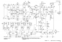
I have included the schematic for the input card for clarity.
I have noticed that the negative input has less distortion (by as much as 6 dB) than the positive input. if you lok t the schematic the difference is that the negative input goes to the inverting side of the differential stage U9. I think the issue is the common mode limits of that opamp and stage. Next step is to find which opamp handles the common mode the best. Also need to go through the circuit and determine the noise floor. Mine all are limited to varying degrees by second harmonic distortion. The input circuit has enough before getting to the notch filter to be the limit.
Also interesting is the "autorange/overload" circuit, U6 and U1. It looks pretty simple to emulate.
The early version 1120 had a 3V output circuit using a pair of 5534's and an active ground follower running off the common power supply.
I guess the mil spec that created (and paid for the development) added 16V open circuit and 8V into 50 Ohms as output requirements. They isolated the whole oscillator and used optoisolators to communicate. It uses a 12bit DAC to steer the voltage on an analog multiplier to fine tune the box. The coarse is caps and resistors switched via FETs. The effective resolution seems to be 5 full digits and its accurate since the output is fed back into the internal frequency counter and the micro steers it all to the target frequency.
This beast can deliver 8V into 50 Ohms to 140 KHz. That is the origin of the poweramp module on the back. I think that, upgraded with something like AD797's and using Scott's cap trick could be quite good. However, there are unknowns that always bite doing these tricks.
Boonton always suggests replacing the main filter caps first. They do age fast since they cook back there.
Attachments
I have included the schematic for the input card for clarity.
I guess the mil spec that created (and paid for the development) added 16 V open circuit and 8 V into 50 Ohms as output requirements.
Thanks--do you happen to have the schematic for the output stage you mention too?
I have noticed that the negative input has less distortion (by as much as 6 dB) than the positive input. If you look at the schematic the difference is that the negative input goes to the inverting side of the differential stage U9. I think the issue is the common mode limits of that opamp and stage. Next step is to find which opamp handles the common mode the best.
Same behaviour is observed for the SYS-2722 (as far as I recall the other way 'round, Bruce surely knew about it and avoided it at least for unbalanced sources), and I agree that common-mode distortion is very likely the cause. The AD797 is, to my best knowledge, the IC opamp of choice if low common-mode distortion is asked for. Even better were a diff amp topology which avoids significant common-mode swing to begin with.
Samuel
Thanks--do you happen to have the schematic for the output stage you mention too?
Here it is: http://www.diyaudio.com/forums/equipment-tools/175147-re-greening-heathkit-ig-18-a-2.html#post2339479
Samuel
Yes the 2nd is where the money is for the 1130 as well.
I build my own 400Hz hp filter that sits on the filter board, and it seems to work OK (passed the cal numbers) yet when I activate it, the 2nd harmonic increases by several dB. So I win in the lf hum, lose in the 2nd
Demian is that also your experience with the filter?
I'm also looking for improved replacements for those integrated switches in the notch circuits LF13201 iirc. They have rather high Ron and the Ron also varies considerably over signal level.
Jan
Attachments
I build my own 400 Hz hp filter that sits on the filter board, and it seems to work OK (passed the cal numbers) yet when I activate it, the 2nd harmonic increases by several dB.
But that's after the notch filter, no? Should not have any significant effect on distortion there. Perhaps some crosstalk (e.g. through the power supply) from it? That'd need to be rather substantial though...
Samuel
But that's after the notch filter, no? Should not have any significant effect on distortion there. Perhaps some crosstalk (e.g. through the power supply) from it? That'd need to be rather substantial though...
Samuel
No the filter set comes after the autoranger, but before the notch....
Jan
No the filter set comes after the autoranger, but before the notch...
Then the filter needs to be designed for low distortion. As far as I understand, the design you're using is taken from a HP analyzer? Those have the filters after the notch and surely aren't designed for low distortion. Can you post the schematic?
Samuel
Then the filter needs to be designed for low distortion. As far as I understand, the design you're using is taken from a HP analyzer? Those have the filters after the notch and surely aren't designed for low distortion. Can you post the schematic?
Samuel
Samuel, attached the filter board schematics and the 400Hz hp I build.
Demian already noticed that replacing U8 by a FET input lowered the distortion and he attributed it to lowering the current through the intergrated switches (LF13201).
Jan
Attachments
This is low or high distortion from the point of view of this thread?
I would say this is low.
What are you measuring this with. What's your setup?
Samuel, attached the filter board schematics and the 400Hz hp I build.
Demian already noticed that replacing U8 by a FET input lowered the distortion and he attributed it to lowering the current through the intergrated switches (LF13201).
Jan
If the the switches are suspect you could remove one or two and jumper them.
Or just jumper them if it's safe to do so and test this. I would do this before considering a replacement switch.
In the Boonton the plug in filters are before the notch. It may be to facilitate SINAD measurements on noisy channels (where the money is). The HP 8903 is similar. If I measure distortion within an octave of the cutoff the distortion goes up. Higher and its OK. The high pass is quite sharp.
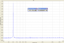
Keep in mind that the box is specified to -80 dB THD+N and can get close to 100 dB with a little care. Freshly tweaked I can get .0006% around 1 KHz with around 3V in.
What I like is the generator accuracy (very close to a precision calibrator) and the ease of use. It also supports closed case calibration for many parts and the GPIB stuff works well. If the 2nd harmonic can be excised it would be really nice.
Monkeying around with the tuning elements can backfire. It does a selftest on turnon and may exit with a failure if the switches don't work right. I know that's true for the generator.
The AD797 is, to my best knowledge, the IC opamp of choice if low common-mode distortion is asked for. Even better were a diff amp topology which avoids significant common-mode swing to begin with.
Samuel
Have you updated your magnum opus on opamp measurements with some of the new ones? I have gotten impressive results from the LME49990 and it seems less fussy than the AD797 (not to mention way cheaper than the AD797 or LT1115 low noise opamps).
Any suggestions for a diff amp with low common mode when starting from a single ended source? I don't see an obvious option. The closest would have an inverter engaged when using a single ended source.
In the Boonton the plug in filters are before the notch. It may be to facilitate SINAD measurements on noisy channels (where the money is). The HP 8903 is similar. If I measure distortion within an octave of the cutoff the distortion goes up. Higher and its OK. The high pass is quite sharp.
Keep in mind that the box is specified to -80 dB THD+N and can get close to 100 dB with a little care. Freshly tweaked I can get .0006% around 1 KHz with around 3V in.
What I like is the generator accuracy (very close to a precision calibrator) and the ease of use. It also supports closed case calibration for many parts and the GPIB stuff works well. If the 2nd harmonic can be excised it would be really nice.
Monkeying around with the tuning elements can backfire. It does a selftest on turnon and may exit with a failure if the switches don't work right. I know that's true for the generator.
There are some improved pin compatible switches like the ADG441 l'm going to try. Another option is a small Reed plugin board but l'm not they may be too slow.
Jan
This is low or high distortion from the point of view of this thread?
It is pretty low... about a step away from ShibaSoku and AP 2722. But, is it accurate measurement at those levels?
What is the hardware and software, please. can it be duplicated easily and/or reasonably low cost?
Thx-RNMarsh
In the Boonton the plug in filters are before the notch. It may be to facilitate SINAD measurements on noisy channels (where the money is). The HP 8903 is similar. If I measure distortion within an octave of the cutoff the distortion goes up. Higher and its OK. The high pass is quite sharp.
In active filters using nfb topologies... at the corners of the filter, the fb is less and thus distortion increases.
Just a small point of interest, perhaps.
-RM
- Home
- Design & Build
- Equipment & Tools
- Low-distortion Audio-range Oscillator