As far as the oscillator, I built my own 35V non-regulated outboard power supply, which was actually putting out closer to 37V at 35mA. This caused the oscillator’s local power supply to run a little too warm for my comfort; you could really see drift of circuit performance as the entire pcb warmed up. The TL431’s were running around 55-60C absolute. So a 100 ohm resistor in series was sufficient to bring voltage down to 34.7V, where the shunt power supply was much more happy and cooler.
Your thoughts?
So, Victor's oscillator is sensitive to supply voltage? I was hoping to run it off of 4X 9V batteries (36V). Well, I suppose that's not a good idea because 9V batteries are anything but... Maybe 3X 12V lead acid batteries? sigh... probably not a good idea either.
Those numbers are in the same range as I was getting. There are resistors (carbon composition) that are worse and many other passives are much worse.
I would propose replacing the resistors with a current source for the power supply. I have use this with good success. Use the High voltage version of the LM317. It also provides short circuit protection and contant performance as the supply fluctuates. Just insert in series with the supply and bypass or reduce the values of the 100 Ohm resistors.
I would propose replacing the resistors with a current source for the power supply. I have use this with good success. Use the High voltage version of the LM317. It also provides short circuit protection and contant performance as the supply fluctuates. Just insert in series with the supply and bypass or reduce the values of the 100 Ohm resistors.
Attachments
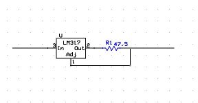
The performance will change as the FET warms up. Takes a few minutes to stabilize. This is typical of all of these systems. With the 100 Ohm resistors the shunt regulators will go from little dissipation to a lot with a small variation in supply voltage. That's why the current source (really a current regulator) is preferable. You also get really good supply isolation.
The LM317 + 4 9V batteries would be about ideal. No ground loops or AC leakage to deal with. The 9V battery should give a continuous 24 hours of operation. Remember to turn it off and you could get months of operation.
The LM317 + 4 9V batteries would be about ideal. No ground loops or AC leakage to deal with. The 9V battery should give a continuous 24 hours of operation. Remember to turn it off and you could get months of operation.
Fine suggestions. I am fairly certain with a shunt setup like this the quality of the outboard supply is less critical than the overall dissipation resultant. I can set up a CCS easy enough, but at this point the oscillator in its current state is the highest hanging fruit.
Those numbers are in the same range as I was getting. There are resistors (carbon composition) that are worse and many other passives are much worse.
I would propose replacing the resistors with a current source for the power supply. I have use this with good success. Use the High voltage version of the LM317. It also provides short circuit protection and contant performance as the supply fluctuates. Just insert in series with the supply and bypass or reduce the values of the 100 Ohm resistors.
Just to be clear, you're talking about the two 100 ohm resistors R32/R33?
What current do you have your LM317 circuit set to? I can get constant current diodes in SMD that could possibly be soldered in place of at least one of the resistors, but they come in specific current ratings. I can't remember how much current this oscillator draws so they may not make one large enough. Is it 35mA?
The LM317 needs a minimum voltage drop in order to function. I think it's about 3V, in the same range as a CRD. So, doesn't the battery supply need to be 35+3V at least? If I remove the resistors entirely then there's 3.5V right there.
Attachments
Last edited:
[QUOTESo by the numbers, my low-Q notch filter performs as follows:
2nd: +30.9 dB
3rd: +34.9
4th: +36.7
5th: +37.7
6th: +38.3
7th: +38.7
8th: +39.0
9th: +39.2[/QUOTE]
If I have understood your notch filter design as being passive without feedback into the bottom of the leg, the low Q will cause the notch to attenuate the second H by about 9db and the third H by about 5db. So you will need to adjust your measurements to have accurate results.
Just to be clear, you're talking about the two 100 ohm resistors R32/R33?
What current do you have your LM317 circuit set to? I can get constant current diodes in SMD that could possibly be soldered in place of at least one of the resistors, but they come in specific current ratings. I can't remember how much current this oscillator draws so they may not make one large enough. Is it 35mA?
The LM317 needs a minimum voltage drop in order to function. I think it's about 3V, in the same range as a CRD. So, doesn't the battery supply need to be 35+3V at least?
I calculated for 25 mA. That is what the circuit draws, including the shunts. The 317 will work down to close to 2V, maybe less. You have 1.25V for the adj that is the real limiter on minimum voltage. I know the LM 317 is stable used this way. There is 5V drop across the two 100 Ohm resistors so you can shunt or replace them with something like 10 Ohm resistors and have plenty of compliance with 4 9V batteries.
25 mA is too large for a current diode and the heat output would be a problem. Don't put two in series or one will be useless since the current is defined by the smallest current limiter. any others will collapse to a minimum voltage. You could use them in parallel. That gets pricey pretty quickly.
They make a 20mA diode, but the minimum drop is 4.5V ($1 each). It's surface mount. I could parallel a 15 and a 10 (about $2.50 each). Maximum voltage across the diodes is not a problem. But, maybe the LM317 will work just fine. Thanks for the tips.
OOOPs sorry, missed a post.... Nice work -- did you add in the harmonic attenuation of the passive notch? That would raise the 2nd by 9.5dB and the 3rd by about 5.5dB, with lesser amounts for the rest.
Absolutely, I thought that was stated fairly clearly. It's possible my math is wrong, but did take the notch into account.
Absolutely, I thought that was stated fairly clearly. It's possible my math is wrong, but did take the notch into account.
So it seems, and the performances of such a simple circuit are quite impressive indeed, although there is a lot of HF noise - most of it is certainly accounted for by your spaghetti setup
") , nevertheless quite a few of HF harmonics (up to 20 kHz or more) seem related to the fundamental: is it true?
, nevertheless quite a few of HF harmonics (up to 20 kHz or more) seem related to the fundamental: is it true?Generally speaking, I'm not a fan of the Wien Bridge, but at a first glance this novel level controlling scheme would apply fairly well to a Bridged-T 2-opamps topology - I think I'll give it a try.
L.
I calculated for 25 mA. That is what the circuit draws, including the shunts. The 317 will work down to close to 2V, maybe less. You have 1.25V for the adj that is the real limiter on minimum voltage. I know the LM 317 is stable used this way. There is 5V drop across the two 100 Ohm resistors so you can shunt or replace them with something like 10 Ohm resistors and have plenty of compliance with 4 9V batteries.
25 mA is too large for a current diode and the heat output would be a problem. Don't put two in series or one will be useless since the current is defined by the smallest current limiter. any others will collapse to a minimum voltage. You could use them in parallel. That gets pricey pretty quickly.
I'd like Victor's opinion on this modification, since it's his design. Victor? Maybe I send him a PM.
I got my oscillator yesterday. It looks good. Thanks Victor!
@DemianUpdate on the Victor oscillator- Running overnight the distortion seems to have dropped. The second harmonic is now almost -140 dB. the higher are still lower in level at around -150 dB. I'll try to check the calibration at these low levels to make sure there is no nonlinearity affecting the readings. The Shibasoku AG16 is a little better but not much better. Essentially these are "perfect" oscillators for virtually any application.
__________________
Demian Martin
Product Design Services
Have you measured performance of the 11 or 12khz oscillators yet?
For kicks, I measured the output of my DCX2496 (1.65V rms) , which is modded by using a Jensen JT-11-DMPC directly connected to the D/A pins. Significantly higher distortion than Victor’s (though still not too bad):
2 = -99 dB
3 = -107
4 = -123
5 = -109
6 = 0
7 = -121
THD = 0.0013%
Not too bad numbers... I have one of the DCX2496 - planning to use it this winter when I am stuck indoors. Right now, I need to measure better than most instruments can do but dont want to spend a small fortune on a new AP. Think I'll go the route Demian has gone.... need to see at least a clean -130. What test system did you use to measure the harmonics?
Last edited:
@RNMarsh -- I don't want to flog this overmuch, but if your measurement needs involve harmonic amplitudes, and you can live with an upper fundamental of 15 to 20kHz, then using a simple active Twin-T filter (to reduce the fundamental while leaving the harmonics unattenuated) between the source and the sound card will allow measurements down toward -140dBu.
I use the T-T with an EMU 0204 external USB sound module and it is very good with respect to noise, but due to using delta-sigma conversion, has a rising noise floor above 30kHz, which compromises the results in that area of the spectrum. Several contributors here have used this method with various sound cards, and it works very well for most of the audio range, especially if the distortion components of interest are low-order.
I use the T-T with an EMU 0204 external USB sound module and it is very good with respect to noise, but due to using delta-sigma conversion, has a rising noise floor above 30kHz, which compromises the results in that area of the spectrum. Several contributors here have used this method with various sound cards, and it works very well for most of the audio range, especially if the distortion components of interest are low-order.
adc
Thank you. I have a AP system One with DSP and it isnt good enough any more. I do need an alternative to the newest AP. I want to have an all portable system... no sound cards in a cpu box.
Is the EMU-0204 thier best or is there another model or brand that would be even better -- what is the best? And where can i find the schematic of the T-T you are using? I want to make this as P-n-Play as possible.
Thank you for the info. -Richard
@RNMarsh -- I don't want to flog this overmuch, but if your measurement needs involve harmonic amplitudes, and you can live with an upper fundamental of 15 to 20kHz, then using a simple active Twin-T filter (to reduce the fundamental while leaving the harmonics unattenuated) between the source and the sound card will allow measurements down toward -140dBu.
I use the T-T with an EMU 0204 external USB sound module and it is very good with respect to noise, but due to using delta-sigma conversion, has a rising noise floor above 30kHz, which compromises the results in that area of the spectrum. Several contributors here have used this method with various sound cards, and it works very well for most of the audio range, especially if the distortion components of interest are low-order.
Thank you. I have a AP system One with DSP and it isnt good enough any more. I do need an alternative to the newest AP. I want to have an all portable system... no sound cards in a cpu box.
Is the EMU-0204 thier best or is there another model or brand that would be even better -- what is the best? And where can i find the schematic of the T-T you are using? I want to make this as P-n-Play as possible.
Thank you for the info. -Richard
- Home
- Design & Build
- Equipment & Tools
- Low-distortion Audio-range Oscillator