Random thought --- The possibility of harmonics being from here to there in level doesnt include the probablity of actually being that wide as the uncertainty suggests it could be.
Just as a string of resistors rarely measure the max of all tolerances (uncertainty). Its usually nearer the nominal value.
So, although harmonics Could Be from here to there in value, it rarely will actually be that far off. In other words, I tend to believe the measurement as shown, first and not worry about the uncertainty of what it 'could' be.
Just a quirk of mine I guess from standards lab work.
Thx-RNMarsh
Last edited:
I get a brain cramp trying to visualize what phase means when comparing fundamental to harmonic. Does 0 degree phase mean they all start at the same point? Or that the peak is at the same point? Which peak? And once you have this info how do you make use of it?
The 725D has an interesting feature where it reconstructs the waveform less the fundamental on the harmonic analysis output. You sync the scope to the trigger out and you can see the residuals. It can give some clues as to crossover/ compression/expansion and where in the waveform it happens. This may be the best shot. If you select a harmonic you may be able to see its relationship on harmonic 1-5. I played with it but found the spectrum more interesting. My shop is a disaster (new floor installed, but project going badly. . .) so I can't really pull up a picture right now. There is a picture on page 3: http://www.tminstruments.com.br/imagens/tm2/373.pdf but it really doesn't explain what is happening.
The 725D has an interesting feature where it reconstructs the waveform less the fundamental on the harmonic analysis output. You sync the scope to the trigger out and you can see the residuals. It can give some clues as to crossover/ compression/expansion and where in the waveform it happens. This may be the best shot. If you select a harmonic you may be able to see its relationship on harmonic 1-5. I played with it but found the spectrum more interesting. My shop is a disaster (new floor installed, but project going badly. . .) so I can't really pull up a picture right now. There is a picture on page 3: http://www.tminstruments.com.br/imagens/tm2/373.pdf but it really doesn't explain what is happening.
You suggestion has occurred to me however most of the popular FFT software apps don't provide phase information. Do you know of some FFT software apps that do?
My SW has this implemented out of the box... just download the evaluation version...
Cheers
Hp
Just boxed-up my PCM4222EVM and ran some tests with Victor's oscillators...
The lowest i can measure is 0.00018% on occasions, which is -115dB THD (no noise)...
The connection is single-ended (negative EVM's input grounded).
The distortion rises rapidly when i turn the voltage on the oscillator upwards, 0.5vRMS gives rather nasty distortion, and it increases to 0.02% at 2.6v RMS sine 1kHz. Lowest THD is at minimum voltage (300mV)
Same thing goes with 10k and 11k oscillators...
Am i in trouble or that's the limits of my ADC? The noise floor is clean at -170db with enough bins (2^20) and averaging.
Last edited:
Reading those paragraphs (right side of page 45), it behooves me to point out that the "full complex number" FFT gives both magnitude and phase angle for each bin. This info can be used to good effect. The fundamental's phase angle will be zero (or some constant, presuming the sampling clock and the sinewave generator are locked, as has been discussed). The harmonic amplitude and phase will be, as the article states, the vector sum of all sources (generator and analyzer). Putting a notch filter between the generator and analyzer at the harmonic frequency will remove the generator's component and reveal only the analyzer's component, and this can be vectorially subtracted from the harmonic amplitude and phase measured without the notch filter, resulting in the amplitude and phase of that harmonic from the generator alone. Repeat for every harmonic of interest, and Bob's your uncle.
Yes, this is a lot of work, and no doubt as others have suggested with doing similar things it's all finicky to get "good" readings at these low levels and stuff. It also depends on getting the raw sampled data into a computer where you can read it and do the appropriate complex FFTs, and vector subtraction of the results.
Several years back I've implemented a similar approach to measure distortion in passives. There are several limitations to it; first, the distortion contribution subtraction is accurate for one operating condition (frequency, level etc.) only--introducing a temporary notch filter in the chain violates this. Second, the distortion contribution must be stable (with time, temperature etc.). In paractice building a passive fundamental notch filter is far more fruitful.
Does Audio-Precision use complex FFT's in their measurements?
Sure. But it's not as simple as just turning on the phase plot. The beginnings of the FFT windows need to be synced to the fundamental frequency, otherwise the phase comes out random.
I get a brain cramp trying to visualize what phase means when comparing fundamental to harmonic. Does 0 degree phase mean they all start at the same point? Or that the peak is at the same point? Which peak? And once you have this info how do you make use of it?
It means that the zero crossing of the fundamental is aligned with that of the harmonic, and the slopes at the zero crossing of the fundamental are the same.
My SW has this implemented out of the box... just download the evaluation version...
Does it support the fundamental sync as outlined above?
Samuel
Does it support the fundamental sync as outlined above?
This feature is currently not implemented. My question on this: how they sync...

Only phase skipping for a certain level...
Hp
My SW has this implemented out of the box... just download the evaluation version...
Cheers
Hp
And what SW would that be?
Just boxed-up my PCM4222EVM and ran some tests with Victor's oscillators...
The lowest i can measure is 0.00018% on occasions, which is -115dB THD (no noise)...
The connection is single-ended (negative EVM's input grounded).
The distortion rises rapidly when i turn the voltage on the oscillator upwards, 0.5vRMS gives rather nasty distortion, and it increases to 0.02% at 2.6v RMS sine 1kHz. Lowest THD is at minimum voltage (300mV)
Same thing goes with 10k and 11k oscillators...
Am i in trouble or that's the limits of my ADC? The noise floor is clean at -170db with enough bins (2^20) and averaging.
Are you using a notch filter?
Just boxed-up my PCM4222EVM and ran some tests with Victor's oscillators...
The lowest i can measure is 0.00018% on occasions, which is -115dB THD (no noise)...
The connection is single-ended (negative EVM's input grounded).
The distortion rises rapidly when i turn the voltage on the oscillator upwards, 0.5vRMS gives rather nasty distortion, and it increases to 0.02% at 2.6v RMS sine 1kHz. Lowest THD is at minimum voltage (300mV)
Same thing goes with 10k and 11k oscillators...
Am i in trouble or that's the limits of my ADC? The noise floor is clean at -170db with enough bins (2^20) and averaging.
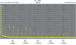
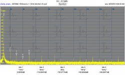
Here are measurements of both the TI PCM4222EVM and the AKD5394A of the same (AG16) generator. There are a number of plots of the same generator that Richard has published here. I believe you are getting about as good as you can from the TI board. I tried a number of optimizations to get it this good. The AKD5394A was worse before I switched to an external master clock. It made less of a difference on the TI board. They are both using the external clock.
Attachments
Thanks!
Victor's oscillator runs on batteries, 4x9v, now soaked down to 32v (been 35v yesterday with the same results). Not yet propertly enclosed - just thrown in an aluminium box which doesn't changes anything. No voltage change on the batteries between max and min output - TL431 works as supposed.
The PCM4222EVM runs off mains, with the supply in the picture,
http://s3t.it/data/uploads/adc_test_psu.jpg
2x2200uF per rail, LM317/337 regs, nothing fancy - just separate steel enclosure with 1.2M multi-coax double shielded wire, with ferrite clamps here and there.
The noise floor is rather clean...
Victor's oscillator runs on batteries, 4x9v, now soaked down to 32v (been 35v yesterday with the same results). Not yet propertly enclosed - just thrown in an aluminium box which doesn't changes anything. No voltage change on the batteries between max and min output - TL431 works as supposed.
The PCM4222EVM runs off mains, with the supply in the picture,
http://s3t.it/data/uploads/adc_test_psu.jpg
2x2200uF per rail, LM317/337 regs, nothing fancy - just separate steel enclosure with 1.2M multi-coax double shielded wire, with ferrite clamps here and there.
No notches, just Victor's ocillator directly connected to PCM4222EVM (hmm, circa 2m microphone wire in between, source impedances aren't matched between negative (which is shorted to ground) and positive (oscillator's output is 600ohm)).Are you using a notch filter?
The noise floor is rather clean...
Attachments
Last edited:
Thanks!
Victor's oscillator runs on batteries, 4x9v, now soaked down to 32v (been 35v yesterday with the same results). Not yet propertly enclosed - just thrown in an aluminium box which doesn't changes anything. No voltage change on the batteries between max and min output TL431 works as supposed.
The PCM4222EVM runs off mains, with the supply in the picture,
http://s3t.it/data/uploads/adc_test_psu.jpg
2x2200uF per rail, LM317/337 regs, nothing fancy - just separate steel enclosure with 1.2M multi-coax double shielded wire, with ferrite clamps here and there.
No notches, just Victor's ocillator directly connected to PCM4222EVM (hmm, circa 2m microphone wire in between, source impedances aren't matched between negative (which is shorted to ground) and positive (oscillator's output is 600ohm)).
The PCM4222E looks very good out to 20kHz. How is it 192ksps?
Haven't tested it @192kHz as my 2nd soundcard drivers (Infrasonic Quartet) which is able to take 192kHz SPDIF died - upgraded and awaiting computer restart.
Currently i'm working with M-Audio Audiophile Firewire, it's maximum is 96kHz.
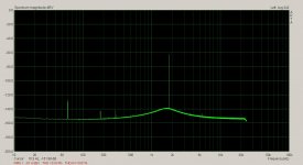
No nasties whatsoever @96kHz, just a few (2-3) dB rise towards the 45kHz. 192 may be worse and we might see it's nastiness at that rise...
Currently i'm working with M-Audio Audiophile Firewire, it's maximum is 96kHz.
No nasties whatsoever @96kHz, just a few (2-3) dB rise towards the 45kHz. 192 may be worse and we might see it's nastiness at that rise...
Last edited:
Lower noise-Jitter (same thing in this case) Plus modulations from shared circuitry in the clocks. I had to modify the board to get the external clock working. I'm not sure anymore what was wrong.
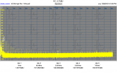
Below is the full spectrum of the measurement I posted earlier at 192 KHz sample rate. You can see the noise rise with frequency.

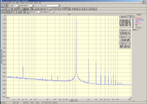
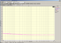
Also, just to make it clear that a lot of resolution is possible with an ADC here is a plot I made of the AG16 with the AK5394A (16 million points, 3 averages, something like 40 minutes to do). The noise floor really is -180 dB and this ADC does not have a rising floor in the operating band. It also shows that getting the resolution up (bandwidth of each bin is really small, something like .012 Hz) gets the noise floor down. You would get the same from a swept spectrum analyzer if you could get one with a .012 Hz bandwidth but it would take much longer to sweep.
With luck I'll have a working shop and can get back to interesting things tomorrow.
Below is the full spectrum of the measurement I posted earlier at 192 KHz sample rate. You can see the noise rise with frequency.
Also, just to make it clear that a lot of resolution is possible with an ADC here is a plot I made of the AG16 with the AK5394A (16 million points, 3 averages, something like 40 minutes to do). The noise floor really is -180 dB and this ADC does not have a rising floor in the operating band. It also shows that getting the resolution up (bandwidth of each bin is really small, something like .012 Hz) gets the noise floor down. You would get the same from a swept spectrum analyzer if you could get one with a .012 Hz bandwidth but it would take much longer to sweep.
With luck I'll have a working shop and can get back to interesting things tomorrow.
Attachments
Let me know when your shop is done and I'll come over.
Improvements for DIY'ers have done pretty good reworking what they have -- rerouting traces, better power supply, rescale the input attenn, grounding and recalib. Things like that.
What can be done to improve the clock situation that will reduce spurious/residual tones? Maybe not as good as a dedicated external clock but better than what is used/done now.
Last edited:
Lower noise-Jitter (same thing in this case) Plus modulations from shared circuitry in the clocks. I had to modify the board to get the external clock working. I'm not sure anymore what was wrong.
Below is the full spectrum of the measurement I posted earlier at 192 KHz sample rate. You can see the noise rise with frequency.
View attachment 349690
Also, just to make it clear that a lot of resolution is possible with an ADC here is a plot I made of the AG16 with the AK5394A (16 million points, 3 averages, something like 40 minutes to do). The noise floor really is -180 dB and this ADC does not have a rising floor in the operating band. It also shows that getting the resolution up (bandwidth of each bin is really small, something like .012 Hz) gets the noise floor down. You would get the same from a swept spectrum analyzer if you could get one with a .012 Hz bandwidth but it would take much longer to sweep.
With luck I'll have a working shop and can get back to interesting things tomorrow.
Very nice.
I tried for two hours today to get the Praxis software working properly.
I finally gave up.
Let me know when your shop is done and I'll come over.
Improvements for DIY'ers have done pretty good reworking what they have -- rerouting traces, better power supply, rescale the input attenn, grounding and recalib. Things like that.
What can be done to improve the clock situation that will reduce spurious/residual tones? Maybe not as good as a dedicated external clock but better than what is used/done now.
What spurious noise.
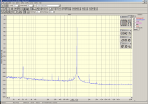
Got a new multiplier design and stable leveling loop. Much better than the lamp one.
3 Vrms measuring 0.00001192% THD give or take a dB.
Attachments
Last edited:
- Home
- Design & Build
- Equipment & Tools
- Low-distortion Audio-range Oscillator