If you increase the resolution on the analyzer the noise will drop and the pesky harmonics will come creeping back out of the noise. You are measuring with a 30 Hz resolution. With the QA400 set to 48 KHz and max resolution the bandwidth is .33 Hz. That should get you down at least 10-15 dB lower.
If we can find a service manual for the 725 I expect mine needs a tuneup (20+ years). It also predates a lot of emi/rfi issues like cell phones.
If we can find a service manual for the 725 I expect mine needs a tuneup (20+ years). It also predates a lot of emi/rfi issues like cell phones.
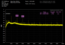
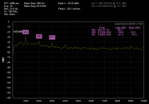
Here is a plot of my KH4400. This is from the monitor output. The top line is -90dBc. The fundamental is at -120 dB the second harmonic is at -128 and the third is -131. this is with a .3Hz resolution. The second plot is at 23 Hz resolution which makes everything look much more wonderful.
The KH4400 is box stock except for tweaking the second harmonic as low as I can and the addition of the external sync input (which I need to work on). It measures THD+N as -110 dB/.0003%, THD at -120 (.0001%) (400Hz-30KHz). More than good enough for most measurements.
The KH4400 is box stock except for tweaking the second harmonic as low as I can and the addition of the external sync input (which I need to work on). It measures THD+N as -110 dB/.0003%, THD at -120 (.0001%) (400Hz-30KHz). More than good enough for most measurements.
Attachments
On my KH4400A I get about the same levels-- .00035% THD on the 1K range X1 = 1Khz. But tuned on the x100 range x10 = 1KHz, I can get about half that amount... .00015% THD. I added two trim controls -- replacing one with a 28 turn and added one 10 turn bridged across an existing R. Only changed the osc opamp to LT1468.
Thx-RNMarsh
Thx-RNMarsh
I thing that mostly a coincidence. When the distortion levels of the generator and the analyzer are close you can get constructive and destructive addition because of the phase. Fundamentally your measuring instrument needs to be significantly better than what you are measuring or you can't tell who is who.
For an inexpensive codec the QA400 is doing quite well.
For an inexpensive codec the QA400 is doing quite well.
I hooked up the QA400 to the KH4400A oscillator (thru an attenuator) and when I take the THD of the loop-thrugh test and subtract it from the KH4400 THD, I get the same THD as the 725 says.
Subtracting the THD from a system performance/loop-trough test is completely meaningless and potentially very misleading. As Demian says in the above post and I have stated multiple times in this thread, the analyzer must be specified (or at least otherwise meaningfully characterized) beyond the level of the measurement. The AD725D is not specified at the -140 dB level.
Samuel
The QA400 is fine and like many in its price range, it isnt good enough for anything much below a few dB's better than -100. Maybe -90 if you cant get close to 0dbV input without distortion generated. So, its limited to use with a notch filter between it and the DUT. Which has its own careful issues to deal with at very low levels. The 725 is accurate to about -130dB. beyond that requires more work.... and I intend to do it... especially the noise levels from its internal filters and need a schematic to do much more. But 10dB better seems very do-able. Never-the-less, i can notch out an 2H or 3H as needed from any generator source with my variable frequency B&K passive notch filter.... another project is to add switchable active to it. For example, if a source has 2H dominant at -120, I can null it out into the noise floor of the 725. Then measure to -130-140.
You've really missed the point if you think I need tracablity to NIST on accuracy.... At these levels of interest, relative changes are often good enough if I can see/measure those changes.
I'm looking for the most stream-lined, easiest and simplist way - not necessarily the cheapest - to take a measurement at very, very low levels over as wide a freq range as possible.
Thx-RNMarsh
Last edited:
On my KH4400A I get about the same levels-- .00035% THD on the 1K range X1 = 1Khz. But tuned on the x100 range x10 = 1KHz, I can get about half that amount... .00015% THD.
Thx-RNMarsh
Demian or Samuel -- Arent you curious to try it or explain it to the readers?
-RNM
Last edited:
The QA400 is fine and like many in its price range, it isnt good enough for anything much below a few dB's better than -100. Maybe -90 if you cant get close to 0dbV input without distortion generated.
Thx-RNMarsh
I can get .0003% from -3 dBFS to about -20 dBFS with the QA400 and my interface. For almost anyone on DIYaudio and most professional/commercial applications that's more than enough. And for around $200 + around $100 for the interface max.
Going below that level is really a research project on a par with measuring time in nS/year. If you are doing exotic research it can be important. If you are troubleshooting your homebrew amp and its not enough then you are in exalted territory indeed.
I know... you've said that several times. It IS a research project. There (arent there?) are technologists around here capable of it. When Scott Wurcer was challenged to do a super descrete opamp - he rose to the occassion and did a beauty.
100 -110dB is fine for a lot of things. Not for SOTA products though.
I know its hard. All the easy stuff has been done. I really do appeciate the details that goes into such precision and accurate measurements. remember, I worked in a Secondary standards lab tracable only to NIST. If you can appreciate that, then you can appreciate the fact that I understand how complex ANY sota effort is. Can you prove to NIST that your measurement of an attenuator at 2 GHz was accurate to .001dB (one thousandth of a dB)? Can you appreciate what was involved and how long it took to get to that level? I did. And, managed the technical engineering side of many large and complex physics research projects for 20 years at LLNL. Not to mention the 3 years at ft Monmouth school in communications electronics and shift maintenance supervisor for Europes largest microWave relay site at Frankfurt, Germany. yada yada yada.
Today, as a technical manager, not an expert in THD measurements and audio osciallators... I would hire them. Arent they here? I appreciate the details, believe me, I am just not interested in knowing every one of them. That is for the experts.. not for me. Where are they? It appears to be too hard to do for no money or just lack of interest? Thats OK. I have plenty of other things to involve myself in. be back when I found something more practical. meanwhile, I will continue to explore the existing technologies thru what has been commercially available to find the technology limits and areas of weakness to exploit for further gain.
Thx-RNMarsh
Last edited:
I can get .0003% from -3 dBFS to about -20 dBFS with the QA400 and my interface. For almost anyone on DIYaudio and most professional/commercial applications that's more than enough. And for around $200 + around $100 for the interface max.
I'll build the interface for its portablity factor. When can we order the pcb from you?
Thx-RNMarsh
Demian or Samuel -- Arent you curious to try it or explain it to the readers?
-RNM
Rick when you switche ranges and tune to the same frequency you have a different set of RC components. The cap is larger and resistor smaller in the lower range. Think about the change of voltage across the components and consider the components distortion under these conditions.
You will get the same effect from the 339a oscillator in two different ranges tuned to the same frequency.
Dave-- hi... i knew you would know the answere but wondered if others did. They should at least try it on their own oscillators to get lowest thd.
yes, I noticed it on the 339A and for the reason you state AND because some opamps are at their optimum in a particular Z range. Maybe others will try it on thier oscillator.
To take it a step further --- the RC values should stay in the optimum range for lowest thd..... --should be limited to a smaller range of R values as part of mod or new design.
-RNMarsh
Last edited:
Dave-- hi... i knew you would know the answere but wondered if others did. They should at least try it on their own oscillators to get lowest thd.
yes, I noticed it on the 339A and for the reason you state AND because some opamps are at their optimum in a particular Z range. Maybe others will try it on thier oscillator.
To take it a step further --- the RC values should stay in the optimum range for lowest thd..... --should be limited to a smaller range of R values as part of mod or new design.
-RNMarsh
Well I'm quite sure both Samuel and Demian know too.
Didnt seem like it. But good to say outloud so ALL readers know and can make necessary mods to their own equipment for best performance.
BTW -- the AD725D THD is spec'ed to be greater than -120dB (5Hz to 5KHz). I see it here on mine as -128dB. Lets just call it -130. Not too far away from -140 max possible goal.
So, a worthy goal for a generator THD at least to -130dB.
Thx-RNMarsh
BTW -- the AD725D THD is spec'ed to be greater than -120dB (5Hz to 5KHz). I see it here on mine as -128dB. Lets just call it -130. Not too far away from -140 max possible goal.
So, a worthy goal for a generator THD at least to -130dB.
Thx-RNMarsh
Last edited:
On my KH 4400A I get about the same levels-- .00035% THD on the 1K range X1 = 1 kHz. But tuned on the x100 range x10 = 1 kHz, I can get about half that amount... .00015% THD. I added two trim controls -- replacing one with a 28 turn and added one 10 turn bridged across an existing R. Only changed the osc opamp to LT1468.
Demian or Samuel -- Arent you curious to try it or explain it to the readers?
I'm not quite sure why this should be of particular interest for me--even the commercial oscillators I'm using are roughly an order of magnitude better than the lower figure you quote... But if it is of help for others a few thoughts (don't have a schematic for the 4400A, so just general remarks):
* As David already noted, you have different passives in each case, so their distortion contribution will be different.
* Different switches are on/off, so their distortion contribution from on-resistance and voltage-dependent off-capacitance will be different.
* There might be time constant switching in the level detector, so the effect from level detector ripple might vary.
* The loading of the opamps is different, and so the magnitude of crossover distortion and possibly layout effects from harmonics in the supply current.
* The source impedance seen by the opamps is different, so the influence of common-mode and nonlinear AC input bias currents will change.
* Capacitive and inductive crosstalk at the harmonics between various oscillator sections will change.
And don't even start to think that just because the distortion at the oscillator output is effectively lower, all the individual contributions must be lower too. It is just as likely that one particular contribution increased and thereby cancelled another better, which results in overall increased performance.
If you want to know what really happens--look at each contribution in isolation (hm, didn't I say that before?).
Samuel
It IS a research project. There (arent there?) are technologists around here capable of it. When Scott Wurcer was challenged to do a super descrete opamp - he rose to the occassion and did a beauty.
Just to put this comparison into perspective: Designing a new discrete opamp which outperforms any available IC opamp WRT distortion in the audio frequency range (and does otherwise well too) would be a matter of a few days, with one or two board revisions and not much if any need to consult the literature. Designing a 10 Hz-100 kHz oscillator which advances the state of the art in THD/THD+N has kept me (more or less) busy for several years. Certain sub-circuits have seen as much as six board revisions, and the litererature I've read specifically for this project must have reached hundreds of pages. Of course it could be just me overlooking the obvious.
Samuel
Thank you for helping spell out the many issues so all readers have an inkling of the issues. I chose to go with existing products' designs as much of those details have already been worked out.
The topology between the 4400 and the next gen model 4402 is completely different and the 4402 is much lower in THD and more easily tuned to even lower levels when more modern opamps are used throughout.
Then too there are some other Japanese makes and models which have slightly different approaches with spec'ed distortion levels that are even lower than KH spec'ed levels. Some with descrete circuit designs for the osc. And, they are not expensive on the used market. Just hard to find.
To get low distortion at relatively low cost is something we all want and taking an existing product and tuning it up -- whether its analog or digital has been rewarding and fruitful.
Thx-RNMarsh
Last edited:
Just to put this comparison into perspective: Designing a new discrete opamp which outperforms any available IC opamp WRT distortion in the audio frequency range (and does otherwise well too) would be a matter of a few days, with one or two board revisions and not much if any need to consult the literature. Designing a 10 Hz-100 kHz oscillator which advances the state of the art in THD/THD+N has kept me (more or less) busy for several years. Certain sub-circuits have seen as much as six board revisions, and the litererature I've read specifically for this project must have reached hundreds of pages. Of course it could be just me overlooking the obvious.
Samuel
Seems like you are the right person. Are you under NDA or otherwise unable to produce some of your work here for DIY'ers... even hard core ones? Or, would you like to commercialize your work? Or, both?
Thx-RNMarsh
Last edited:
Are you under NDA or otherwise unable to produce some of your work here for DIY'ers... even hard core ones? Or, would you like to commercialize your work? Or, both?
I don't think there's much commercial potential for such equipment--Bruce Hofer knows how to design the next generation top-notch AP, and besides that there's probably no company interested in pushing the limits of audio analyzer WRT distortion resolution.
My oscillator design will be made available for DIY when I'm happy with it, just don't want to push out half-ready stuff.
Samuel
- Home
- Design & Build
- Equipment & Tools
- Low-distortion Audio-range Oscillator