I not getting the same spectra as you are. You need the monitor output to look at that.
I said i am using the monitor output. Looking at just the residual from the notch.
I have 2 ports.... one labelled Normal (the one I am using) and the other labelled Analyzer (which appears to be an FFT port).
Does your analyzer have 2 ports?
Good question was what are you measuring for a noise floor via your port?
-Richard
Last edited:
Lamp Multipler
I have the lamp multiplier in isolation.
This is some noise spectra of the output with no input connected from the SVO and no notch.
The multiplier has a large Vc to multiplier zero offset.
The yellow overlay is the EMU0204 with input shorted.
All measurement is referenced to 0dB FS. 192ksps 131072 points and linear smoothing.
The second image is with no Vc input so the lamps are cold at minimum R. The noise gain of (6.8) of the multiplier is at maximum in the non inverting mode. The signal gain is maximum. This represents the minimum range frequency of the OSC.
The first image is with maximum input Vc. The lamps are brightly lit. The noise gain is at minimum and the multiplier is in inverting mode at maximum signal gain. This represents the maximum range frequency of the OSC.
Attachments
Last edited:
with and without the multiplier lamp?
6db to 2-3 db upper freqs. Does not add much to the noise.
We can infer from this that most if not all oscillators do not have a great deal of noise from their multiplier?
[I know thats a stretch if you havent done same with several types of ultra-oscillators/multipliers].
-145dB noise floor?
Thx-RNMarsh
Last edited:
I said i am using the monitor output. Looking at just the residual from the notch.
I have 2 ports.... one labelled Normal (the one I am using) and the other labelled Analyzer (which appears to be an FFT port).
Does your analyzer have 2 ports?
Good question was what are you measuring for a noise floor via your port?
-Richard
Also - info> I am using a 30Hz bandwidth resolution at 1KHz per/Div. Smoothing On.
And Log vertical scale (10db/div).
[no FFT averaging to remove noise-- just filtering]
-RNM
Last edited:
Lamp Multipler
Every thing here is the same as the above post but with the addition of Victor's 1kHz oscillator.
The osc output is 1Vrms into the multiplier input.
The pics show the natural attenuation of the multiplier at min and max Vc.
Every thing here is the same as the above post but with the addition of Victor's 1kHz oscillator.
The osc output is 1Vrms into the multiplier input.
The pics show the natural attenuation of the multiplier at min and max Vc.
Attachments
The last plot was from the monitor port using the fft. The first pair are FFT vs. swept on the distortion analyzer port. That port is just harmonics with the noise removed. The phase relationship of the harmonics is retained as well. you can reconstruct them using the trigger jack to trigger the scope which can help identify sources of distortion by their relationships.
I'll look at the monitor output shortly.
I'll look at the monitor output shortly.
with and without the multiplier lamp?
6db to 2-3 db upper freqs. Does not add much to the noise.
We can infer from this that most if not all oscillators do not have a great deal of noise from their multiplier?
[I know thats a stretch if you havent done same with several types of ultra-oscillators/multipliers].
-145dB noise floor?
Thx-RNMarsh
It's not bad. I am happy with this but we can do better.
With 20dB of decoupling between multiplier and OSC I think the noise is out of the way.
I'm at the measurement limit for what I have so further improvement will be difficult to confirm without more gear.
That was my problem too and why I got a couple ADC's to follow along with you. Then this ShibaSoku analyzer dropping into my lap and then I started using it. It has allowed me to see the effects of changes I could make/try to oscillators.
But if the adc system is as good or even almost as good, it is small, more portable and allows for better integration with files/software on a PC. I would use both.
I do need assurance that the drivers will work on old and new PC's (XP and WIN7 and maybe soon Win8) without hitches. The software must have its drivers kept updated to always be compatable with Microsoft upgrades and changes.
Thx-RNMarsh
Last edited:
Neither the 7L5 nor the Wavetek have a narrow enough bandwidth to see into the noise. These are first the distortion analysis out showing the relative amplitudes of the harmonics without the noise and second the monitor output with the narrow bandwidth of the QA400 allowing a much deeper view into the noise. The distortion analysis is a reconstructed signal with the fundamental around 500 Hz regardless of the input frequency. The generator is set to 1KHz at 10V. It has a source impedance of 600 Ohms. In the first picture 0dB is -100 dB, the second 0 dB is - 90 dB out (I think, I need to check). With .6 Hz bandwidth the noise floor is about -160 dB. Translating that to meaningful SNR or equivalent nV/RtHz shall we say "is an exercise left to the reader".
Attachments
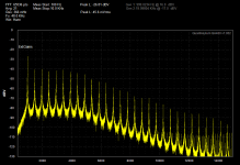
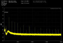
Neither the 7L5 nor the Wavetek have a narrow enough bandwidth to see into the noise. These are first the distortion analysis out showing the relative amplitudes of the harmonics without the noise and second the monitor output with the narrow bandwidth of the QA400 allowing a much deeper view into the noise. The distortion analysis is a reconstructed signal with the fundamental around 500 Hz regardless of the input frequency. The generator is set to 1KHz at 10V. It has a source impedance of 600 Ohms. In the first picture 0dB is -100 dB, the second 0 dB is - 90 dB out (I think, I need to check). With .6 Hz bandwidth the noise floor is about -160 dB. Translating that to meaningful SNR or equivalent nV/RtHz shall we say "is an exercise left to the reader".
"Translating that to meaningful SNR or equivalent nV/RtHz shall we say "is an exercise left to the reader". "
Oh thanks a lot make me do all the work.
Kidding of course.
. With .6 Hz bandwidth the noise floor is about -160 dB. Translating that to meaningful SNR or equivalent nV/RtHz shall we say "is an exercise left to the reader".
Ok. Thats what I said the noise floor was awhile back... about -160dB. Check.
For my purposes at this time, I am finding ways to lower noise and thd of oscillators.
Both a clean source and an analyzer that can be as good as the source are needed.
Im looking forward to seeing what davada can do to get his -145dB even lower.
The add-on interface is very welcome and great that it doesnt affect the thd/noise issue.
This is all good for DIY.
Thx-RNMarsh
Last edited:
I am looking at the notched output of residual harmonics from the analyzer monitor output. I am using an analog swept wave filter type analyzer - HP-3580A.
The monitor output is scaled to the analyzer range selected with a normalized output level of 1v rms = full scale (fs) of the range selected. The range is on its lowest from a ShibaSoku AD725D analyzer which is -110dB (.0003% fs). The noise floor from this monitor port is about -160dB re fs.
The dynamic range of the HP is >85dB on its 0db/1v range.
The signal level from the generator being measured is 7v rms.
Thx-RNMarsh
Hi Richard, thanks.
I also like and trust my HP 3580A. I use it to get below the noise of the distortion analyzer as you do by feeding it the residual output from the analyzer. In my case it is my THD analyzer rather than the ShibaSoku.
With such an arrangement, the distortion floor of looking at an incredibly good oscillator will be the distortion floor of the analyzer. The same thing holds true for inferring the oscillator noise. In other words, the analyzer must be substantially better than the oscillator under test, both in regard to THD and noise.
In my case, my distortion analyzer section is made with virtually the same kind of circuitry as the oscillator, using SV architectures. Indeed, the amplitude and frequency autotune circuits use the same kind of JFET control elements. So, to first order, my analyzer section tends to have similar THD and noise limitations as the oscillator. Indeed, when I did my last round of upgrades about a year ago, I seem to recall ending up believing that the analyzer section was the limiting factor.
Which brings me to this question. You have shown some stunning results with your oscillators using the arrangement you described, with the ShibaSoku as the analyzer. I know that the ShibaSoku has impressive specs, but is it really better than the oscillators you are measuring, both for THD and noise?
Am I missing something here?
Cheers,
Bob
Hi Richard, thanks.
With such an arrangement, the distortion floor of looking at an incredibly good oscillator will be the distortion floor of the analyzer. The same thing holds true for inferring the oscillator noise. In other words, the analyzer must be substantially better than the oscillator under test, both in regard to THD and noise.
I seem to recall ending up believing that the analyzer section was the limiting factor.
Which brings me to this question. You have shown some stunning results with your oscillators using the arrangement you described, with the ShibaSoku as the analyzer. I know that the ShibaSoku has impressive specs, but is it really better than the oscillators you are measuring, both for THD and noise?
Am I missing something here?
Cheers,
Bob
You arent missing anything re noise and the analyzer. I cant go below the noise floor of the analyzer monitor output, naturally. It become a natural limitation using this Fast Track method and would only work with a very good analyzer system... If I had to, I would rent the best analyzer I could to do the oscillator upgrades. Otherwise it is a very slow process of single tone measurements back and forth sort of thing. Which ultimately would be the final solution after the present method.
The oscillators and analyzers of the past thought none would ever need to read below .001-2% and left it there. Today with SOTA opamps and ADC/DAC systems, measuring with the old tools isnt good enough and measuring with lab cludges is too slow. So its upgrade time. The topologies are Ok... some better than others but the general upgrades with best parts now available can and has done wonders.
This morning, I recieved anothr opamp and when i used it (at 1KHz) with existing new opamps was able to drop both 2H and 3H into the generator noise floor at -155dB. BUT it was higher than the other opamps tried at 10KHz.
The generator noise is close to the analyzer noise of -160db so the accuracy is not so good anymore on the noise part but still fine for getting the THd lower iinto the noise - what ever it is.
Clearly with the opamp changes this morning, the two opamps' harmonics are doing their own cancelling -- phase shifts no doubt at work (one bipolar and one fet input opamp). This is another clue as to how to cancel harmonics once the opamps are as good as they can be. And, if the Twin-T R/C values were optimized for the newest opamps it would help more. But its a fast and good process to get to the bottom line.
")
Thx-RNMarsh
Last edited:
What is the equivalent input noise of the analyzer? If the noises are near 5 nV/rtHz or less you won't find significant improvements in noise easily. The input attenuator will be the roadblock. I did notice the noise floor is lower for a 1V input than a 10V input suggesting the attenuator is out of the circuit at 1V.
What is the equivalent input noise of the analyzer? If the noises are near 5 nV/rtHz or less you won't find significant improvements in noise easily. The input attenuator will be the roadblock. I did notice the noise floor is lower for a 1V input than a 10V input suggesting the attenuator is out of the circuit at 1V.
Already very significant improvement has been made. Now, however, as I get under 10dB from the test system noise, it will be harder. Therefore -> My reason to go in and lower the noise of the ShibaSoku which I started to do. And, I know where i can get 6-12 db improvement. waiting for Ic's to arrive. At that point I can go ahead and get a few more dB's from the generator and thats about it for this go-around.
The system is optimized at 1v input but the noise floor is still higher than it has to be compared with newer opamps. It isnt sufficiently lower at 1v to make me Not want to decrease it further.
Thx-Richard
Last edited:
If the front end of the 725 isn't quiet enough you won't get there. That is the first place to quantify.A quick check on this one indicates that the input noise is -110 dBV in a 100 KHz bandwidth. That would be the equivalent of 5000 Ohms. (Useful tool for this- Thermal Noise Calculator ) And that translates into 8 nV/RT Hz or -160 dBV in a 1 Hz bandwidth.
Without the circuit diagrams we are limited in what we can do to improve this. My guess it that the input attenuator and protection circuits are the source of the limitation. The input transistors are probably significantly quieter than this.
Without the circuit diagrams we are limited in what we can do to improve this. My guess it that the input attenuator and protection circuits are the source of the limitation. The input transistors are probably significantly quieter than this.
I am about to start looking at the analyzer some more. The input card looked like it was all discrete but a further look will reveill more when I remove it. The filters are always noisy for some reason... Will get into it more soon. Without schematic it i slow going but still doable for certain basic things - especially analog portions.
Have you disconnected the protection to see if noise drops? Shorted the input pot/attenuator to see if noise drops/changes as you think it might?
Thx-RNMarsh
Have you disconnected the protection to see if noise drops? Shorted the input pot/attenuator to see if noise drops/changes as you think it might?
Thx-RNMarsh
Last edited:
yep its all discrete analog design to get the performance they felt was needed. Only one opamp IC (5534 - maybe servo?) to replace. All the input switching is done with hermetically sealed relay contacts.... Will be looking at in more detail-- Notice the K389. Wonder what the topology is?
-Richard


-Richard
Last edited:
- Home
- Design & Build
- Equipment & Tools
- Low-distortion Audio-range Oscillator