5VDC in 1500VAC out- $5
See here:
http://tinyurl.com/8q9uo
Manual here:
http://tinyurl.com/9johs
Easily multiplied to 3 kVDC or higher with a few diodes and capacitors.
I_F
See here:
http://tinyurl.com/8q9uo
Manual here:
http://tinyurl.com/9johs
Easily multiplied to 3 kVDC or higher with a few diodes and capacitors.
I_F
Great find.
The CCFL inverter in general seem to be a standard DC to AC converter. Even though they are made for a fluorescent lamp, there isn't any special starting voltage or current produced, just high voltage AC. Small, cheap and readily available from many online sources. The inverter you linked even has provision for soft on-off switching.
Here's a pdf file describing CCFL inverter design.

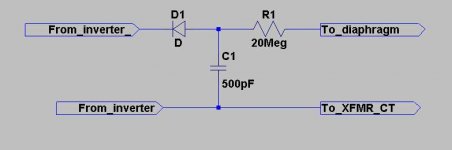

It is generally not a good idea to put rectifiers in series without using some voltage equalizing resistors. If the diodes are not well matched, the reverse voltage across each diode (when they are not conducting) may not divide equally and you may exceed the reverse breakdown voltage limit of one or more of the diodes in the series chain.
For this application I would think that 1Meg resistors in parallel with each of the under-rated diodes should work OK, but they should be high voltage type resistors.
High voltage resistors are not the same thing as the parts you get at radio shack. Most resistors will not work well much above 500-1000 V. When I say they won't work well, I mean they will self destruct, even if used within their power rating. The high voltage causes some sort of chemical changes that cause the resistance to increase dramatically. Your circuit will work fine for a few weeks, then suddenly you'll have problems and won't be able to figure out why until you check the resistors and discover them open.
The best thing to do here is find properly rated HV diodes (rectifiers- same thing) and use them. HV resistors are a little expensive. But don't forget to use an HV resistor for the current limiter (10M-50M ohm).
I_F
The best thing to do here is find properly rated HV diodes (rectifiers- same thing) and use them.
Well thanks, that was my ? if they were the same, I can find them no problem.
Mouser
Hmmm,
I have 10M current limiting resistor in series with output as well. But I think it was standard kind. I should check to make sure its still working after about a year of listening. I guess even if it went bad, I wouldn't be able to tell unless I shocked the bejesus out of myself.
Thanks for the input. Do you have links or sources for high-voltage rated resistors of this type?
-Wes
Hi Folks,
my experience with HV supllies tells me, that there is no need for specific hV resistors for the output.
I like to explain an investigation i performed on that topic:
1. I measured the voltage output of the transformer at 200 Volts AC
2. I put a 100K resistor in serie to the trafo output and the voltage multiplier input.
3. I connected the power supply and measured the voltage drop of the resistor at 10 Volts, which reduced to 2 Volts when the capacitors were fully loaded after a few seconds. This means the constant current is about 2/100000 = 0,00002A.
4. lets assume that current will flow at the HV output as well (but it won't be the same due to loss in rectifiers and capacitors). If your output resistor is 10M, the voltage drop of that resistor is 10M*0,00002A=200 Volt , which isn't critical for standard resistors.
5. In addition you can put e.g. 3 resistors in serie. This reduces voltage drop to 3,3M*0,00002A=60V for each resistor.
Certainly the formula i used are not perfectly valid for AC , but even 2 times the current is not critical.
Since 15 Years i never had a break down of HV supply due to resistor failure although i use standard metal-oxide types rated at 0,6Watts.
Regards, Capaciti
Capaciti said:Hi Folks,
my experience with HV supllies tells me, that there is no need for specific hV resistors for the output.
I like to explain an investigation i performed on that topic:
1. I measured the voltage output of the transformer at 200 Volts AC
2. I put a 100K resistor in serie to the trafo output and the voltage multiplier input.
3. I connected the power supply and measured the voltage drop of the resistor at 10 Volts, which reduced to 2 Volts when the capacitors were fully loaded after a few seconds. This means the constant current is about 2/100000 = 0,00002A.
4. lets assume that current will flow at the HV output as well (but it won't be the same due to loss in rectifiers and capacitors). If your output resistor is 10M, the voltage drop of that resistor is 10M*0,00002A=200 Volt , which isn't critical for standard resistors.
5. In addition you can put e.g. 3 resistors in serie. This reduces voltage drop to 3,3M*0,00002A=60V for each resistor.
Certainly the formula i used are not perfectly valid for AC , but even 2 times the current is not critical.
Since 15 Years i never had a break down of HV supply due to resistor failure although i use standard metal-oxide types rated at 0,6Watts.
Regards, Capaciti
I would not expect the current (ie- power) to be an issue.
A high-voltage resistor isn't usually a high power rated device. It is a HV rated device by virtue of its chemistry and physical construction. They are typically made rather long, to keep the metal leads separated as much as is practical, and I assume they are made of materials that will not break down after thousands of hours of exposure to high voltage fields.
Whatever the actual mechanism, carbon film resistors do fail when they are subjected to high voltages. Maybe metal oxide resistors do not suffer the same fate as carbon film resistors.
HV type resistors cost only a dollar or two, and only one is needed per bias supply, so I prefer to use them rather than spend extra time troubleshooting in the event of a failure.
I_F
If the resistor in question is the current limiting one in series with the diaphram, I'm guessing it would be less of a trouble shooting exercise and more of a very rude awakening in the event of a failure during discharge.
I agree with you. Especially when saftey is concerned. It is probably worth the extra few bucks to sub them out.
-Wes
I agree with you. Especially when saftey is concerned. It is probably worth the extra few bucks to sub them out.
-Wes
Hi,
as i mentioned the voltage drop is just 100 V. Thats the difference between resistor input and output and only that counts. It doesn't matter where high voltage excists, as long the resitor doesn't "see" it. And it doesn't.
I just mentioned the rated power of 0,6 watt in order to explain that a standard metall-oxid type does the job.
But i agree, it is no failure to use specific high voltage resistors - sh.. will happen as Murphy told us.
regards, capaciti
Although in the event of a rapid diaphram discharge (suppose from some moron touching it with a metal stick) the voltage across the limiting resistor is now very high. (Although the power might still be within range)
I guess this doesn't relate to a gradual breakdown over time due to the high voltage, but rather to an instantaneous failure.
-Wes
I guess this doesn't relate to a gradual breakdown over time due to the high voltage, but rather to an instantaneous failure.
-Wes
- Status
- This old topic is closed. If you want to reopen this topic, contact a moderator using the "Report Post" button.
- Home
- Loudspeakers
- Planars & Exotics
- low cost, small, safe bias supply