Mooly said:So now it's back to 00940")
What can I say ? I'll have to build it one of these day but I don't have an oscilloscope at my disposition (not easily at least). I'll have to wait till september.
If I follow you correctly, the tl081 is a guarantee of trouble-free operation and decent performance while the ne5534 is better but requires some care.
Did you try to put a small film cap from the supply to ground pins of the tl081 (with a small value resistor in serie, to avoid oscillations) ?
Hi,
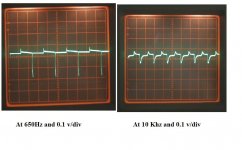
There were so many possibilties to try really. All I can say is the 5534 did need care. Using the circuit of post #22 with decoupling caps removed (all the 100 mfd) the 5534 was totally unstable, the whole circuit just oscillated. Removing these is something you would never do I know but it was interesting. A TL071 or 81 -tried both- was totally stable. Back to the 5534 and adding just C6 stopped the instability, but only if it were near the pass transistor collector. Move it down the board and oscillation began but at a lower amplitude. To be fair the circuit as posted works well, the only part that I would investigate is C2. I found with no C5 fitted (all others in place) that as the input to the pass transistor passed through about 16 volts or so the circuit would break into oscillation, increase the voltage a bit and it stopped. Removing C2 seemed to stop this. From what I remember it didn't affect the regulation at all either.
The TLO71 was totally stable, keep to within it's current sinking ability and this seemed the best choice of the IC's I tried really.
A further refinement may be to add a more precise voltage reference (for pin 3 of OpAmp) fed from the LM317 output to eliminate temperature drift etc with the zeners.
Good luck with it all
Well, the loop gain here is 2 (with the output feedback divided down to half) and the 5534 is internally compensated for a gain of 3 or higher, so that is not a good choice here, unless you use external compensation.
Secondly, the output capacitor forms an integral part of the loop stability. You need a minimum of capacitance and NOT a foil cap with zero ESR. If you look at the data sheets of some of those low-dropout integrated regs, they often spec 10uF at the output with a *minimum* of 0.1 ohms ESR. The cap stabilizes the loop and the ESR kills the oscillations, so to say (not entirely correct but you get the point).
So, to really be able to judge the performance in real apps, you need to include the output cap value and type.
Lastly, some of that ringing will be coming from the wiring inductance in your test-bench setup. If you use a good pcb layout, with correct pick-off points for the feedback and the grounding of bot the ref and the feedback divider at a common, clean ground point, you will measure different, better, behaviour.
Jan Didden
I've been having some fun with Eagle. This suggested layout is NOT to make a proper pcb but an outline for prototyping on "stripboard". C4 and C5 are to be soldered directly on the resistors leads by example. C8 and R7 could be soldered under the board directly on the opamp pins. I think the sense points are clean ??
Jan: I think it was Fred Dieckmann who suggested the use of film caps in serie with a small resistor at the output of regulators, in order to keep good performances at HF while keeping the regulator stable ?
Jan: I think it was Fred Dieckmann who suggested the use of film caps in serie with a small resistor at the output of regulators, in order to keep good performances at HF while keeping the regulator stable ?
Attachments
00940 said:I've been having some fun with Eagle. This suggested layout is NOT to make a proper pcb but an outline for prototyping on "stripboard". C4 and C5 are to be soldered directly on the resistors leads by example. C8 and R7 could be soldered under the board directly on the opamp pins. I think the sense points are clean ??
Jan: I think it was Fred Dieckmann who suggested the use of film caps in serie with a small resistor at the output of regulators, in order to keep good performances at HF while keeping the regulator stable ?
Yes, that is possible. But it's not a very smart way to do. The advantages of a film cap, low ESR and low dielectric absorbtion, are negated by the ESR.
A regular electrolytic has the required ESR 'build in' and is much lower in price, of course.
BTW Nice layout, good grounding scheme.
Jan Didden
- Status
- This old topic is closed. If you want to reopen this topic, contact a moderator using the "Report Post" button.