A tapered TL for the ES140
It's not necessarily true that a high-Qts driver won't work well in a TL, just as it is not necessarily true that a low-Qts driver will. That said, the only real drawback to the ES140's performance is its lowish sensitivity. I modeled a 50-inch long line tapered at just over 11:1. The system is tuned to ~33 Hz. The center of the ES140 is located 10 inches from the beginning of the line. The line has a beginning cross-section of 6"W x 10"D and an ending cross-section of 6"W x 0.875"D. The terminus, the line's exit, is at the end of the line also with a cross-section of 6" x 0.875". The first 2/3 of the line's length is filled with polyester fiber at a density of 1 lb/ft3. I've attached the modeled system bass response (red line); this is the anechoic response for a 2.83-volt input (re: 1 meter) that does not include room effects or baffle step losses and shows an F3 of ~39 Hz. This was modeled with 0.5 ohms added in series with the driver to approximate the resistance of a crossover inductor in series with the woofer (which both reduces its sensitivity a bit and increases the Qts a bit), ending with an output and sensitivity of just over 84 dB SPL. An input of 15-20 watts will increase the output SPL to ~97 dB which is pretty much the limit on driving the ES140 before excursion becomes an issue.
Paul
Attachments

Pkitt,
That is actually very similar to what I came up with too and now take -5dB off for baffle step and you are at 79dB. I also got that broad trough at 2.5k. Your design looks a bit smoother than mine but then I have baffle diffraction included.
That is actually very similar to what I came up with too and now take -5dB off for baffle step and you are at 79dB. I also got that broad trough at 2.5k. Your design looks a bit smoother than mine but then I have baffle diffraction included.
I think limiting BSC to 4 dB is quite adequate (I always use only 3-4 dB in my personal builds) and would end up with a final sensitivity of 80 dB (I made it clear in my post that baffle step losses weren't included).
Paul
Paul
I agree sometimes one can get away with 4dB loss. Thanks for the simulation though - what is the final volume and how would you fold it and what are the final dimensions?
The net line volume is just under 1 ft3. If I were building it I would make it a single-fold line in a box with an internal height of 25" and a depth of 11.375". Even though I modeled it with a width of 6", I'd make the box a bit wider, say 6.25" or so, to add some additional volume to compensate for any consumed volumes, like from the driver, braces (the angled line divider's consumed volume is already accounted for in the modeling), and a crossover assembly. Oh, a total of about 13 ounces of polyester filling will be needed. The 1/2" thick line divider would be attached to the top of the cabinet with its front side 10" behind the baffle and its back side 0.875" in front of the rear panel. This bottom of this divider would be located equidistant from baffle, internal bottom and back panel. The ES140's center would be located 10" below the internal top, with a tweeter above it, and the terminus (slot exit) would fire out the back at the very top.
Paul
Paul
I hope I'm not trolling this very interesting thread. Damped transmission lines are an interesting part of the repertoire. Strengths and weaknesses no doubt.
It's the Transient Perfect aka Harsch design bit I'm struggling with.
I've seen this 24db/octave bass with 12dB/octave tweeter before. It's in the Snell/Audio Note 8" bass plus tweeter designs.
But I am deeply confused about the time alignment issues, and I really don't get the complex crossover (below) being used here at all. Most of the elements are redundant. Just fiddling about really, you follow?
xrk971, with deep respect for a very interesting construction, can you explain what is going on here in simple words that I might understand?
A summary, if you like.
Attachments

System7,
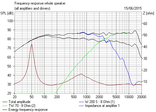
Great questions and you are not trolling at all. You are aware of my other Harsch XO thread so all I am doing is applying that to a tapered TL with damping applied to produce a gentle fall-off slope in the bass which translates to low group delay. The un-damped TL has a response similar to a vented bass reflex alignment with a double impedance peak. The TL has a lot more vent cross sectional area though so bass output flows a lot less impeded. It achieves low tuning via quarter wave TL vs a BR volume resonator. By adding damping strategically and monitoring frequency response and measuring resulting impedance peaks, one can adjust the bass fall off slope and trade off some extension for less group delay. You know you have the damping right when the impedance peaks get squashed into almost a single broad bump with two little "horns" where the peaks used to be. In this state, the bass extension is still very good and the group delay approaches that of a sealed box. I have measured a GD of 6.5ms at 50Hz. Some of that delay is from the XO filter.
The cabinet is a folded 48in long TL with a taper ratio of 5:4:3:1.5 - tapering produces a deeper tuning frequency than a straight TL. This one is tuned to about 55Hz.
On the XO, I implemented in minidsp active 2 way which lets me dial in time delay for Harsch XO time alignment. This requires the tweeter to be delayed by half the period of the cycle at the XO frequency to allow the Harsch XO to be quasi time aligned. I tried to implement this passively and it's my second passive XO design so a lot of work is needed still. I tried to remove bumps and wiggles which is why it's so complicated. With passives however, the only time to effect such a large millisecond range delay is to physically step the baffle and out tweeter back.
On the speaker you reference above, it does have similar 24/12 slopes - but by its nature of being passive and flat baffle - there is no way it is a time aligned quasi transient perfect speaker. So not technically a Harsch XO.
To do this passively - it makes more sense to spend a little more on a smoother mid bass driver to save on having to spend so much on all the coils and caps needed to flatten it. Not a problem with minidsp. I would use an AC130F1 if I were to redo this for a passive XO. That driver is flat and easy to make work in a 2 way.
Hope that helps.
X
Last edited:
OK, thanks for a very prompt answer. 🙂
This stuff is hard. Are you saying we can do this sort of asymettric Harsch 12dB/24dB slope with regular filters and a bit of time alignment like this "improved" Snell?
It's a weird thing, but sometimes you just hit on a filter that makes the music leap out live, if you follow. According to Lynn Olson, even cabinet geometry and rounding the corners, has a huge effect on time coherence:
Nothing to stop anyone from developing a modern successor to the Ariel, using drivers in current production. For myself, I'm not interested, because I have a personal stash of replacement Scan-Speak tweeters and the very last Vifa 5.5" drivers. (I contacted Madisound before they were sold out. By the way, I don't get a discount from them, or from Vifa.)
If you want an Ariel-like sound, here are the items I would concentrate on:
* The midbass driver should be musically pleasing without any help from the crossover or equalization. In other words, it should be similar to a fullrange driver but without the 2~5 kHz artifacts and roughness in the breakup region. This is a key requirement.
* When looking at the CSD of the tweeter or midbass, there should be as little energy storage in the 1~10 kHz region as possible. This is also a key requirement, and the area where many exotic-cone drivers fall down pretty badly.
* A primary goal of the system is to have an impulse response decay characteristic as good or better than well-regarded electrostats. The cabinet must have large-radii left and right edges in order to get this kind of impulse response, and the bass enclosure must be free of standing waves.
* Although 1st-order crossovers offer the possibility of accurate square-wave reproduction (provided the tweeter is recessed, which brings its own set of problems), excursion control for the tweeter is quite poor. (Excursion for direct-radiators increases at a rate of 12 dB/octave as frequency is lowered, so 1st-order crossovers actually result in increasing excursion below the nominal highpass crossover frequency. It takes a 12 dB/octave highpass to merely keep excursion constant, and 18 dB/octave to reduce excursion.)
I find that low-Q 2nd-order electrical networks offer a reasonable compromise between group-delay error and control of tweeter excursion. A tweeter that is moving too much will sound raspy (or blurred, depending on design) when the program material has a dense spectrum and starts to get loud. That's part of the reason exhibitors at hifi shows like to use demo material that has a sparse HF spectrum ... audiophile blues, for example. Many high-end speakers collapse when you give them full-spectrum symphonic or choral music at concert levels.
* The system is optimized for transient response, but not leading-edge transients nor accuracy with square waves. The optimization is for the most rapid decay characteristic, and one that is free of resonance as it decays to zero. Most drivers have problems with this. A few drivers have good decay characteristics, and subjectively, as a group, they have a "sweet" sound, and are not zingy, raspy or mechanical sounding.
* Part of the purpose of the large-radii cabinet edges is to be able to see the favorable decay characteristics of the driver when looking at the CSD. If the edges are sharp, this alone generates so much clutter in the time domain that it's difficult to see what the driver is doing.
* Since my days at Audionics, I design crossovers so the acoustical phase match between drivers (at crossover) is 5~10 degrees or better. This can be confirmed by temporarily reverse-phasing the tweeter and looking for a null (at 2 meters distance) that is at least 25 dB deep.
* The overall spectral curve is smooth with a 1~2 dB down-tilt from 100 Hz to 10 kHz. In most rooms, this gives a subjectively flat sound with pink-noise excitation.
* For quick subjective assessment, I primarily use pink-noise, with orchestral and choral music as a cross-check. Rock music and movie soundtracks can provide a quick impression of dynamics and "snap", but this is heavily influenced by outside factors like the recording and the state of tune of the rest of the system (DACs, phonograph, power amps, etc).
There! You can design your own Ariel, if you like.

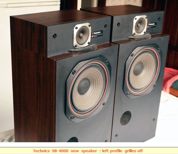
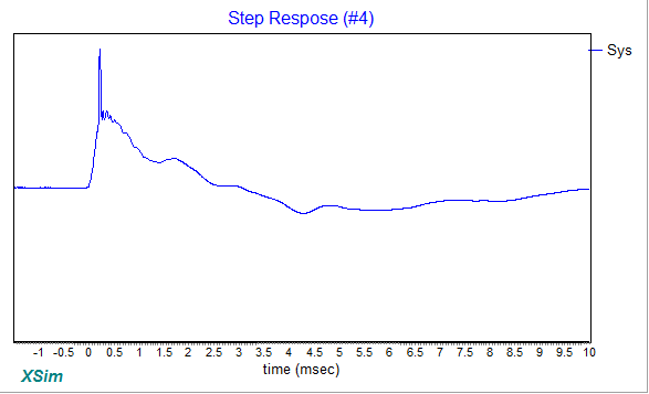
That's exactly what I did with my passive XO design was to make a speaker-level Harsch quasi transient speaker. It does required mechanical setback of tweeter to achieve the time delay though, so it would look just like the Technics speaker. In fact, copying the Technics box and putting your favorite drivers in its place can work well (vary the setback distance). The setback can be determined precisely by making the tweeter top shelf moveable and slide until the sound pops (or verify with step response). If you look at the predicted step response of my passive Harsch XO (with tweeter setback), you will see it resembles the classic right triangle. Very few speakers achieve the ideal right triangle of transient perfection. The Dunlavy SC-IV is perhaps one of the best examples of transient perfection but it is achieved via 1st order filter slopes.
Here is Dunlavy: http://www.stereophile.com/content/...eaker-measurements-part-3#CdBTwbzJsqtlYeDk.97
+1 totally agree.
The multiway transient perfect speaker is actually something rarely experienced by most folks and they don't even know they are missing it. You don't know what you don't know. But once you hear it and experience the visceral realism of what a drum rim shot or even hard strike on a drum skin or grand piano can sound like on a speaker, it's hard to know. Once you know though, it's hard to go back to non transient perfect speakers. I went to listen to some very highly regarded 802 Diamonds but they lacked the transient perfect response. Their XO topology doesn't allow it, so as nice as they sounded in overall dynamic range and low harmonic distortion, did not achieve the realism that a $13k set of speakers should do.
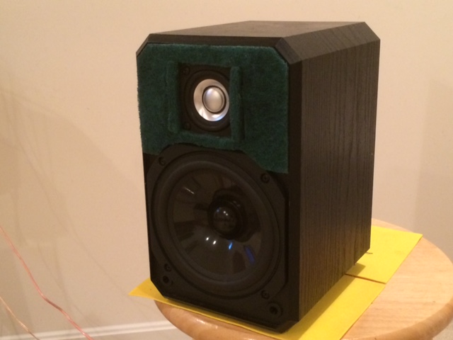
With my mini desktop monitors, I was also able to achieve transient perfect with broad flat response drivers and 1st order slopes:
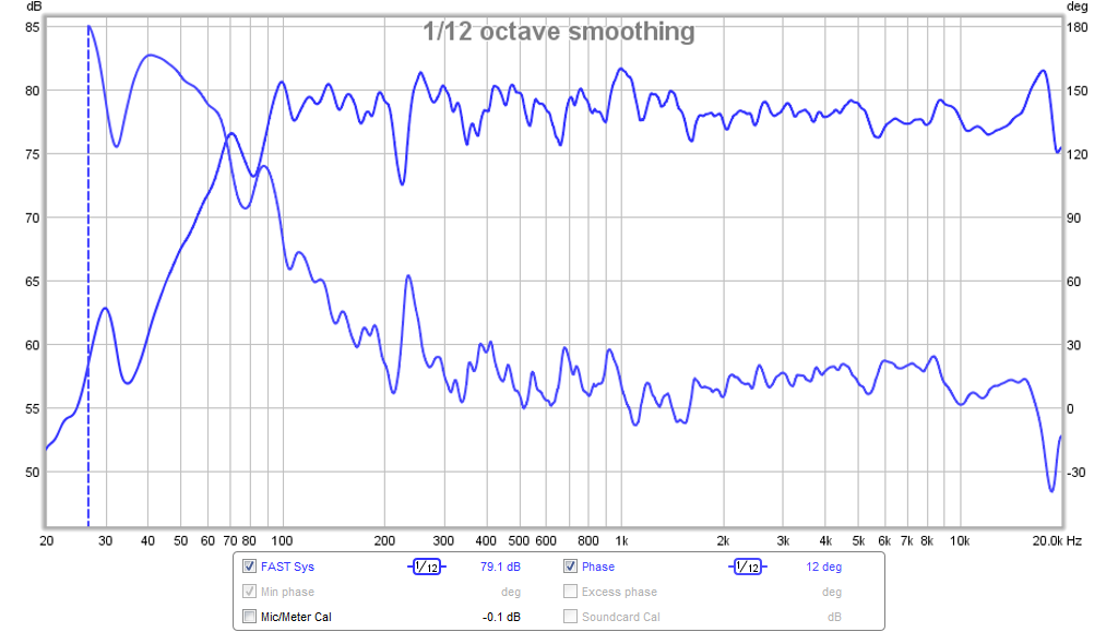
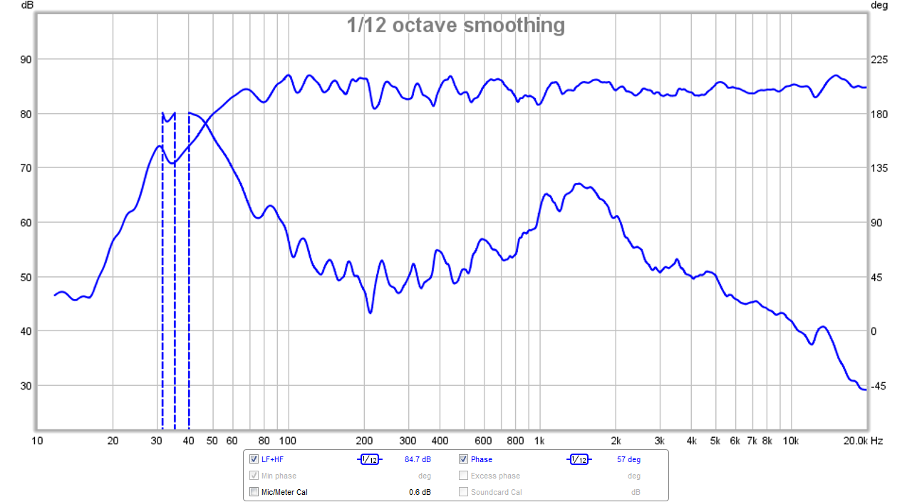
Freq response and phase:
Measured SR:
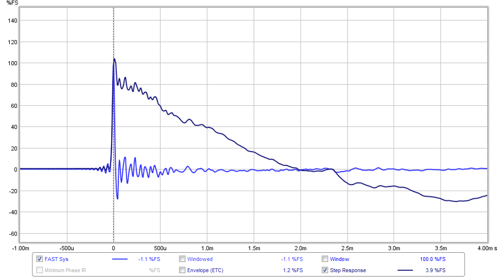
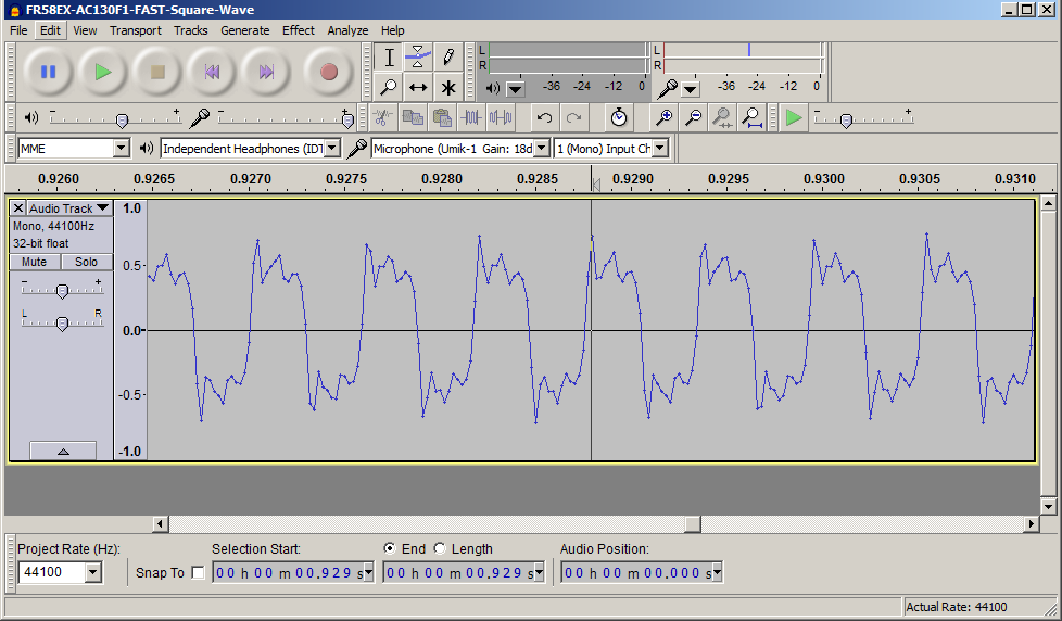
Square wave played at XO frequency:
More info here:
http://www.diyaudio.com/forums/full-range/280331-fr58ex-ac130f1-micro-fast.html
Here is Dunlavy: http://www.stereophile.com/content/...eaker-measurements-part-3#CdBTwbzJsqtlYeDk.97
An externally hosted image should be here but it was not working when we last tested it.
It's a weird thing, but sometimes you just hit on a filter that makes the music leap out live, if you follow.
+1 totally agree.
The multiway transient perfect speaker is actually something rarely experienced by most folks and they don't even know they are missing it. You don't know what you don't know. But once you hear it and experience the visceral realism of what a drum rim shot or even hard strike on a drum skin or grand piano can sound like on a speaker, it's hard to know. Once you know though, it's hard to go back to non transient perfect speakers. I went to listen to some very highly regarded 802 Diamonds but they lacked the transient perfect response. Their XO topology doesn't allow it, so as nice as they sounded in overall dynamic range and low harmonic distortion, did not achieve the realism that a $13k set of speakers should do.
With my mini desktop monitors, I was also able to achieve transient perfect with broad flat response drivers and 1st order slopes:
Freq response and phase:
Measured SR:
Square wave played at XO frequency:
More info here:
http://www.diyaudio.com/forums/full-range/280331-fr58ex-ac130f1-micro-fast.html
Last edited:
An ML-TL version for the ES140Ti
I modeled a 50-inch long mass-loaded TL essentially equivalent to the tapered TL I modeled. The ML-TL has a constant cross-section modeled at 6"W x 4.5"D. The ES140's center is, again, located 10" from the beginning of the line, while the mass-loading port's center is located 3.5" from the end of the line. The port has dimensions of 1.75"D x 3.75"L. The stuffing density is 0.75 lb/ft3 with the first 2/3 of the line stuffed, requiring ~6 ounces of polyester fiber. I've attached the predicted bass response (red line) for an input of 2.83v/1m and with 0.5 ohms added in series with the driver. The advantage of this ML-TL as compared to the tapered TL is a lower F3 in a smaller line volume and a generally smoother response. Also, it's easier to tweak the system tuning via the port's length (this ML-TL is tuned to ~35 Hz). The disadvantage of an ML-TL is that the port's air velocity is significantly higher than that in the terminus of the tapered TL, but there still should not be any audible port noise since the port will be on the back panel if this is built as a single-fold line similar to the tapered TL.
Paul
Attachments

Have you guys seen this new combo from PE? It includes two very nice drivers - the RS180 woofer and DC28F that I have here an a cabinet for $100. You would have to end up going either sealed and LT for the woofer or a bass reflex (yuck). Great value though.
Dayton Audio 7" Two-Way Speaker Starter Kit with Enclosure
A TL could be designed for the RS180 and I predict it would work very well.
Dayton Audio 7" Two-Way Speaker Starter Kit with Enclosure
A TL could be designed for the RS180 and I predict it would work very well.
There's some nice kits available in the States.
Dayton Audio BR-1 6-1/2" 2-Way Bookshelf Monitor Speaker Kit Pair
The cabinet is available seperately too. Designed for Dayton Audio DC28FS-8 1-1/8" silk dome tweeter and DC160S-8 6-1/2" woofer.
Here in the UK, Wilmslow Audio offer a nice reflex 12L cabinet for SS W15 or Vifa P14 with 104mm tweeter. The Mercury.
Back on topic, your Harsch filter must be about 60 degree phase at crossover, eh? Neither -6dB phase-aligned LR2, or 90 degree -3dB BW3.
Quite unusual.
Sys7,
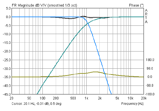
The theoretical phase at XO is detailed in the white paper by Harsch describing the XO. I think it is is theoretically 55 deg and flat above and below for that quasi transient perfect aspect. It's tough to get it flat in reality though as my measured phase if you take the trough to the left to be the baseline - then at XO it is about 60 deg. My phase to the right is deviating downwards and not flat. When you can match the textbook target curves of BW4 and BES2 perfectly - the phase is indeed flat with a 55 deg bump I think. Byrtt showed this with his electronic loop back experiments using a sound card and no speaker.
Here is my measured phase:
Harsch XO white paper: http://petoindominique.fr/pdf/phase.pdf
Last edited:
system7,
Here a fun HARSH study including two zipped attached files that can be opened in free XSim software (download here: http://www.diyaudio.com/forums/multi-way/259865-xsim-free-crossover-designer.html).
First two pictures with just XO point and infinite system bandwidth. Picture 1 raw LP BW4 and HP BES2 as they sum firing in sync without offset, picture 2 have 6,75 inch offset (0,5mS) for tweeter.
Last two pictures with XO point and system bandwidth limit in stop-bands at BW2 20Hz and BW2 20kHz. Picture 3 raw LP BW4 and HP BES2 as they sum firing in sync without offset, picture 4 have 6,75 inch offset (0,5mS) for tweeter.
Study was made by linking a frd-file with right slopes to each of the drivers.
Slopes was created in Rephase as IR wav-file imported to REW then exported as frd-file to link to drivers in XSim.
Have fun tweaking offset and on the fly see traces in plot windows change.
Attachments


Last edited:
Welcome X, also posted same study over your HARSCH XO thread and think we also smile and say great thanks to creators of Rephase/REW/XSim.
More people really should try the Harsch XO. If you have a reasonably smooth responding driver in a 2 way or 3 way and DSP, no reason not to try. Music really has snap and realism again.
I can't help thinking that it would be cool to fold the line so the driver could be in the corner of the enclosure, that way you could build a TMM or MTM, but I can't seem to wrap my head around the the fold, can somebody help?
Last edited:
I was imagening two separate lines in two separate cabinets on top of each other, with a tweeter in the middle, hence the need for a fold with the driver in the end of the box, to get time smallest c-t-c distance. For a TMM you then use one of the boxes for a the 0.5 woofer and have a box with a bass reflex on top.
- Home
- Loudspeakers
- Multi-Way
- Low-Cost PMC-inspired TL Monitor with DC130A and DC28F