Hi,
I have never observed methylene chloride dissolving PVC, at least not within time it takes to evaporate(perhaps several hours to be safe). It's pretty weird you observed this. Perhaps not all grades of PVC are the same and may have different additives.
I think your problem is you want things to go fast") No it won't work that way and with PCB method you no longer have the high reliability of wire esl and possibility to make electrical segmentation.
No it won't work that way and with PCB method you no longer have the high reliability of wire esl and possibility to make electrical segmentation.
@Moray James : Yes I remember you have mentioned the need for lower open area for damping years ago. I used this advice in all panels I build to get open area between 20-30%. BTW your method of using very thin wires might be very good in the case of light louvers but with horizontal cross bars spaced lets say 50 mm apart thin wires are look too flexible. Also I like that PVC insulation is damn bullet proof and will take a lot of abuse till it's damaged.
Best regards,
Lukas.
I have never observed methylene chloride dissolving PVC, at least not within time it takes to evaporate(perhaps several hours to be safe). It's pretty weird you observed this. Perhaps not all grades of PVC are the same and may have different additives.
I think your problem is you want things to go fast
No it won't work that way and with PCB method you no longer have the high reliability of wire esl and possibility to make electrical segmentation. @Moray James : Yes I remember you have mentioned the need for lower open area for damping years ago. I used this advice in all panels I build to get open area between 20-30%. BTW your method of using very thin wires might be very good in the case of light louvers but with horizontal cross bars spaced lets say 50 mm apart thin wires are look too flexible. Also I like that PVC insulation is damn bullet proof and will take a lot of abuse till it's damaged.
Best regards,
Lukas.
It all goes with the passion of R&D !!!!
Yes, I have spent well over $200 on the cost just trying out different materials only to come with a combination that cost under $20 for a few pairs of small to medium sized panels.
But the smile my face when I heard my creation for the First time and still being able to use them 10 years later is PRICELESS!!!
The one method that I want to try some time is the use 30 ga. Kynar coated wire wrap wire.
I have read reports that this stuff works very good as well.
I did some preliminary insulation breakdown tests back in 2003 at the same time I had discovered a Powder coater in my area.
It withstood about 10Kv or more very easily but my PC screens worked out so well, I never tried it.
And then the cost of copper went through the roof shortly after that!!
I will fire up my HV supply sometime soon and get some realtime voltage breakdown measurements using it.
One of the First speakers that I made I used it as a Voice coil glued to a small Diagphragm of about 3" X 5" made out of some Monokote model airplane covering.
I used super glue on it and it didn't effect the the Kynar one bit even when I tried to remove the winding.
The only draw back of that experiment was that it was just to heavy to get any good efficiency out of it.
jer
Last edited:
well the dipping failed. it melts to much and pores alongside the wires. i did do s smal test of glueing a comb made out of trespa on the cnc with hot glue on the ends of a piece of louvre and that looks promissing, i could not pull it off without breaking the styrene. thats good news, because now i might try the way acoustat did there wireing. no need for a jig there, just wires from comb to comb while the panel is concaved. only stupid thing is i bought allot of stiff wire 0.5mm2 wich is usless if i want to try this. i need no stiff wire, and probable thinner say 0.25mm2 has an outside diameter of 1.2 instead of 2mm wich hopefulle sinks better into the frame. also all my cutters are bigger then 1.2 mm so i need to get those as well damn hobby
only stupid thing is i bought allot of stiff wire 0.5mm2 wich is usless if i want to try this. i need no stiff wire, and probable thinner say 0.25mm2 has an outside diameter of 1.2 instead of 2mm wich hopefulle sinks better into the frame. also all my cutters are bigger then 1.2 mm so i need to get those as well damn hobby well the dipping failed. it melts to much and pores alongside the wires. i did do s smal test of glueing a comb made out of trespa on the cnc with hot glue on the ends of a piece of louvre and that looks promissing, i could not pull it off without breaking the styrene. thats good news, because now i might try the way acoustat did there wireing. no need for a jig there, just wires from comb to comb while the panel is concaved.
How do you expect to make wires really straight and have consistent spacing between each other without using a jig?
How do you expect to make wires really straight and have consistent spacing between each other without using a jig?
well dont know about yet i can imagine some combs along the panel until its dry, acoustat did not have any jig, the concaved it and just whent back and forth. then for the glueing they put it in convex shape so the wires stretch even more then when the panel is flat.(they wont stretch but straighten out)
WrineX: Acoustat bonded their wire spacer/jig on to the ends of the louvre grid. I have seen people wrap two face to face louvres with a threaded rod at each end to provide spacing for the wires. The wire wrap then goes around both panels. After bonding the wires the to the louvre they are cut at the ends of the panels to free the two stators from one another,
The use of highly toxic adhesives and solvents is very disturbing as most folks simply do not appreciate how dangerous these products can be. For example using Crazy Glue to bond wires on a large panel. This is a real health hazard. I speak from personal experience. I do not have the fast and simple answer for those who want to achieve fast assembly times. I do have a thought but I have never figured how to implement it for stator construction. If you could plasma treat the inside surface of a styrene or acrylic louvre so that the top surface is carbonized (2-3 molecular thickness layer) then construction would be very simple. You could them encapsulate the stator wires using white glue. Totally non toxic. Multiple thin layers of the encapsulating adhesive would make for a much faster set up time than one single thick layer. Further if you were using a solvent based adhesive then this method would have a lower impact upon the louvre structure as well. The trick to plasma treating the surface of the louvre is keeping the carbon layer so very tin 2 -3 molecules at most otherwise the carbon layer will break off under stress. This type of process is usually done on a high speed web so that the material speed and distance (from the plasma) can be precisely controlled as it passes beneath the plasma discharge. Hand held plasma discharge devices are available but they are small. You could build a unit. I still find this a most interesting idea I just cannot see a simple way to use it to construct ESL panels. Perhaps one of you can. Best regards Moray James.
The use of highly toxic adhesives and solvents is very disturbing as most folks simply do not appreciate how dangerous these products can be. For example using Crazy Glue to bond wires on a large panel. This is a real health hazard. I speak from personal experience. I do not have the fast and simple answer for those who want to achieve fast assembly times. I do have a thought but I have never figured how to implement it for stator construction. If you could plasma treat the inside surface of a styrene or acrylic louvre so that the top surface is carbonized (2-3 molecular thickness layer) then construction would be very simple. You could them encapsulate the stator wires using white glue. Totally non toxic. Multiple thin layers of the encapsulating adhesive would make for a much faster set up time than one single thick layer. Further if you were using a solvent based adhesive then this method would have a lower impact upon the louvre structure as well. The trick to plasma treating the surface of the louvre is keeping the carbon layer so very tin 2 -3 molecules at most otherwise the carbon layer will break off under stress. This type of process is usually done on a high speed web so that the material speed and distance (from the plasma) can be precisely controlled as it passes beneath the plasma discharge. Hand held plasma discharge devices are available but they are small. You could build a unit. I still find this a most interesting idea I just cannot see a simple way to use it to construct ESL panels. Perhaps one of you can. Best regards Moray James.
that sounds fancy wel plasma is not that hard to form i guess, but i dont think its the fastest way. i know the solvents are dangerous and if i go fullscale inside i will use some sort of thing to suck the gasses outside. funny i noticed that acoustat had the sucktion form the bottom of the convier . wich is a nice detail because metheleen is heavier then air might look for some healthy variants while im at it
wel plasma is not that hard to form i guess, but i dont think its the fastest way. i know the solvents are dangerous and if i go fullscale inside i will use some sort of thing to suck the gasses outside. funny i noticed that acoustat had the sucktion form the bottom of the convier . wich is a nice detail because metheleen is heavier then air might look for some healthy variants while im at itThe point with a plasma treated surface is that it has now (no matter what it was before) become carbon (on the surface). The significance is that just about everything will stick to carbon. This is how you can glue two teflon parts together. Trick very trick. Something like a modified version of PVA adhesive similar to the kind used for book binding or a little firmer setting if you like and you can encapsulate wires all day long for just about forever clean as a whistle safe and totally non toxic.
What ever you do keep thinking about this and you are bound to come up with a solution that will work for you. Be as safe as you can and have fun. Best regards Moray James.
What ever you do keep thinking about this and you are bound to come up with a solution that will work for you. Be as safe as you can and have fun. Best regards Moray James.
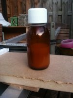
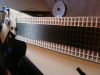
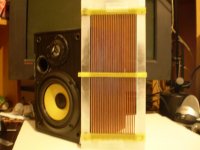
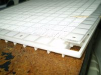
well first try with disolved styrene in methyleenchloride . i got a nice sirop, and for now just for the test if it holds and and wil sag down between the wires. for a real panel i would use smaller wire, smaller spacing, no solid core but stranded so the panel can stretch itself like aucostat. but i had this wire already so just for the test.
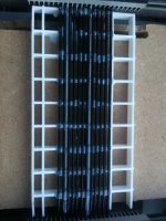
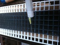
in the bottle is the white sirop, dont breath in! its nasty crap, hence why i do this outside. the glue layers are not verry nicely done, i used a disposable siringe, problem is its affected by the methyleenchloride , because its a plastic syringe, what happend is that the inside of the siringe starts to get sticky, and so i dont have the control of the flow i put out, sometimes it sticks then i push a little harder and then BLOB allot of the stuff ends up on the panel , and drips down. so its not really a beauty i did release the panel after 45 minutes or so. all wires except 2 of the end wires hold. acoustat used combs at each end of the stator so these wires could not get lose and would be nicely tight and snug to the styrene. for me i have to glue the spacer on top of the wire there so its no big deal. i will fix another stator right now, ad some spacers. just to complete the whole tiny ugly test version. and maybe ad some mylar to see how it sounds. (always the fun part, cant skip that one)
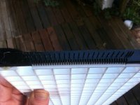
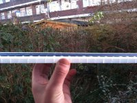
made a second one in half an hour, , damn this is a fast method, well the glue sags pretty nice and overal it looks pretty flat.
in the bottle is the white sirop, dont breath in! its nasty crap, hence why i do this outside. the glue layers are not verry nicely done, i used a disposable siringe, problem is its affected by the methyleenchloride , because its a plastic syringe, what happend is that the inside of the siringe starts to get sticky, and so i dont have the control of the flow i put out, sometimes it sticks then i push a little harder and then BLOB allot of the stuff ends up on the panel , and drips down. so its not really a beauty
i did release the panel after 45 minutes or so. all wires except 2 of the end wires hold. acoustat used combs at each end of the stator so these wires could not get lose and would be nicely tight and snug to the styrene. for me i have to glue the spacer on top of the wire there so its no big deal. i will fix another stator right now, ad some spacers. just to complete the whole tiny ugly test version. and maybe ad some mylar to see how it sounds. (always the fun part, cant skip that one)made a second one in half an hour, , damn this is a fast method, well the glue sags pretty nice and overal it looks pretty flat.
Attachments
Last edited:
Hi,
Are you using a fully plastic syringe? If memory serves well PVC ones having a rubber piston were acceptably resistant to methylene chloride for some time. Nice to see your progress. BTW what are your design goals?
Are you planning to build a hybrid? Full range? Panel size?
Regards,
Lukas.
Are you using a fully plastic syringe? If memory serves well PVC ones having a rubber piston were acceptably resistant to methylene chloride for some time. Nice to see your progress. BTW what are your design goals?
Are you planning to build a hybrid? Full range? Panel size?
Regards,
Lukas.
design goal is hybride with magnepan SMG-C for the lows. to keep all figure of 8 patern. yes i used a fully plastic one. just the ones i could find at the local drugstore. might take a look for PVC ones or i might get a air compressor a metal or plastic tank the resists to the choride, and valve wich i can control with a small voltage, and add it to my CNC machine. just for the fun of it and my health. so i point the nozel on the corner or the panel, hit zero. pump the tank with the choride full of air (must see what presure) then let a relais that normally enables the spindle motor control the valve. write some gcode ,, hit start ! and the glue should look better then the job i did aaah well
aaah wellso i tried some other stuff, i tried the Plastic primer moray james sugested, i used the brand MOTIP a well known paint brand or at least spray paint. one coat on the louvre then wire up the jig but the louvre in place and sprayed 3 times with a interval of 15 minutes. wires wont attach, even worse the louvre seem to break ant critical point it gets sort of bross, suddenly a row collapsed, and then whe i touched the louvre another one collapsed. it seems it is kind of agressive against styren. i also tried the PVA glue methode, it has better results but it is still weak and nog near as perfect as the methelene chloride. biggest problem i have i finding either a pump that can handle the solvent or a magnetic valve that can. dont want to spill allot off this crap to be honest
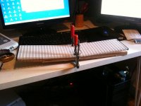
ok here some picture of the setup right now.
i used al the left overs of the styrene panels and put them in a blender, to create small/dust styrene, this disolves faster in the chloride. i got a big bottle of the crap and i only need 2/3 of a syringe (10ml )to do one stator.
still by hand glueing because , i think its to expensive to go automatic.
i have to buy for around 80 euro of fittings and hose (PTFE) and a compressor , and a magnet valve that can handle the chloride (did not find one yet). i used a syringe with a needle witch works pretty nice compared to without a needle. i now pressure a little and becaue i let the needle touche the wires a drop falls between the wire and over.
i made some weird combs with nails so i can wind faster then a comb alonne (pretty tight conrner for a wire), but the comb still dictates the spacing, i hot glue this on the top and bottom of the panel, when winded and glued i reheat the tips of the HPL and the hot glue lets go so i can resuse them on the next panel. so far so good.
im now of to shop for some 2 mm acryl i had some laying around but its to short . im so curious how they sounds compared to other panels i made. expecisally in the distortion department because i still cant believe all my trannies are bad. has to be something with bad panels or sloppy contrustion. these looks promissing.
one last thing anyone has an idea to mate the panels ? i can use glue but i dont preffer to glue them and never get them appart (in one piece)
i used al the left overs of the styrene panels and put them in a blender, to create small/dust styrene, this disolves faster in the chloride. i got a big bottle of the crap and i only need 2/3 of a syringe (10ml )to do one stator.
still by hand glueing because , i think its to expensive to go automatic.
i have to buy for around 80 euro of fittings and hose (PTFE) and a compressor , and a magnet valve that can handle the chloride (did not find one yet). i used a syringe with a needle witch works pretty nice compared to without a needle. i now pressure a little and becaue i let the needle touche the wires a drop falls between the wire and over.
i made some weird combs with nails so i can wind faster then a comb alonne (pretty tight conrner for a wire), but the comb still dictates the spacing, i hot glue this on the top and bottom of the panel, when winded and glued i reheat the tips of the HPL and the hot glue lets go so i can resuse them on the next panel. so far so good.
im now of to shop for some 2 mm acryl
i had some laying around but its to short . im so curious how they sounds compared to other panels i made. expecisally in the distortion department because i still cant believe all my trannies are bad. has to be something with bad panels or sloppy contrustion. these looks promissing.one last thing anyone has an idea to mate the panels ? i can use glue but i dont preffer to glue them and never get them appart (in one piece)
Attachments
Last edited:
Looks Good !!
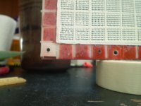
What I did is I glued plastic strips around the perimeter using superglue, and. drilled a hole every 3 to 4 inches or so (every 5 squares) and used a small bolt (#6-32's) to sandwich the stator and diaphragm frames together.
Since you have two squares of spacing use the outside perimeter of squares as this will give you ample room for a charge ring on the inside without contacting to the bolts.
This makes the panel easier to handle while it is operating and not got a accidental jolt form the bias supply voltage from the screws!
Don't waste your money on the Nylon bolts as they won't hold (for long) and will eventually strip out unless you use some bigger ones and this can get quite costly!!
I have used this method for every version of my panels without any issues of repeatability of constant dis-assembley and re-assembly since I First made them in 2003.
First I drill the holes in the stator's and diaphragm frames as they were sandwiched together with some Masking tape to assure perfect alignment of all of the holes.
Having a CNC sure helps with this !!
Then I mounted the Mylar using epoxy to one of the frames (that has the mounting side slightly roughened up) on a piece of glass and then re-drilled the holes in that frame to clear out the excess epoxy.
Go slow at this part because epoxy is gummy when you drill it and it can catch and tear off the Mylar.
Then I re-sandwiched everything back together and heat treated the Mylar for tensioning.
Once you have you proper tension you can take them apart and again and finish with coating the mylar and adding a charge ring if you choose to use one.
One note~Since you have the space you can mask off the outside rows with the bolt holes to keep the conductive coating away from the bolts.
This is something that I wished I had thought about when made my First designs and caused issues when I finally had a Bias supply that could get over 4 or 5Kv and added the charge ring.
I have found that a conductive paint made from Graphite and white glue worked the best as it has no issues with corrosion, else it may not even be necessary to have one for a panel of the size you are working with right now.
You just paint it right on the applied coating and right over a conducting tab made of Aluminium or Copper tape for the Bias connection.
I didn't add one to any of my designs until I refurbished my last set.
If you use an Aluminium tape for the charge ring make sure that you scuff it with some steel wool before you sandwich everything back together.
It is a tedious process with so many screws as the panels get longer but it doesn't take that long to get them apart and back together again.
There is a lot clamping force and I haven't taken the time to see how far I could space the bolts to reduce their count.
I am guessing that some where in the 4 to 6 inch range may work as well.
I have them set for 5" on my new design and it is only 10" long, But the TIG rods give it the majority of its rigidity.
You may find that you will have to re-tension them again once or twice but after that the alignment of all of the bolts once they are all re-inserted will be all that is needed.
And you will now have a panel that you easily change D/S spacing by adding shims in between the diaphragm and stator frames if needed.
Hope this info will help you with your design.
jer
Attachments
Last edited:
Thx gerald, i had the same idea about the bolts, only thing is i only have a spacer of 2 mm, so hope it will hold the whole frame. for starters i try using these clamps i have to see if it works as i would like. , having a cnc is nice, but usually most handy when working with stock material. i could ofc dill some pins in my table so i can reference to the panel and let the ahcine drill the holes. i might do that its less of a lets dril it fast so it will play thing i will try to use doublesides tape for the menbrane, and thanks for the masking pointer!!!, i tend to forget that oine to wich can result in leakage indeed.
i wont be getting 5 Kv bias i guess because me Dc spacing became 0.8mm/0.9 or so 0.2 less then i wanted. my wires are 1.2mm in diameter wich is an odd size, because plastic for spacers usually comes in 0.5 increaments with results in either to big spacing or to close
i will try to use doublesides tape for the menbrane, and thanks for the masking pointer!!!, i tend to forget that oine to wich can result in leakage indeed.i wont be getting 5 Kv bias i guess because me Dc spacing became 0.8mm/0.9 or so
0.2 less then i wanted. my wires are 1.2mm in diameter wich is an odd size, because plastic for spacers usually comes in 0.5 increaments with results in either to big spacing or to close I used a very thin sheet of acetate or Mylar of about .020" to .030" around the perimeter nothing fancy just some thin stuff.
Some thinner .010" stuff may work as well.
Once glued to the grid it was very strong to hold the frames as most of the tension that was created was focused on the sandwiching force.
This way you will gain back the lost D/S offset from the thickness of the wire.
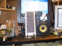
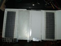
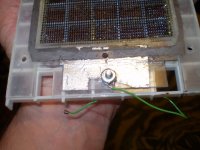
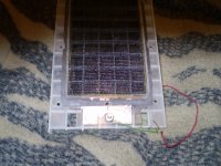
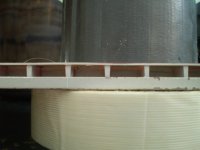
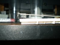
Here are some close up's of the charge ring that I just found and a couple of other panels showing the Plastic strips that I used.
This one shows it to be on the opposite frame that is clamped against the Diaphragm rather than being directly on it, Either way will work.
I just measured them and they were of .030" material.
These panels are 11 years old and I have re-glued the small ones that I have used again, as I used the glue too sparingly and did not use enough.
The black ones were almost (He,he,he) indestructible once I had re-guled them.
Until some thing fell on them and ripped the screen!!
I found that with a panel this small of width, it wasn't necessary to have any clamping force in the middle on the top and bottom so you are good there.
Just along its length is all that is needed.
Cheers !!
jer
Some thinner .010" stuff may work as well.
Once glued to the grid it was very strong to hold the frames as most of the tension that was created was focused on the sandwiching force.
This way you will gain back the lost D/S offset from the thickness of the wire.
Here are some close up's of the charge ring that I just found and a couple of other panels showing the Plastic strips that I used.
This one shows it to be on the opposite frame that is clamped against the Diaphragm rather than being directly on it, Either way will work.
I just measured them and they were of .030" material.
These panels are 11 years old and I have re-glued the small ones that I have used again, as I used the glue too sparingly and did not use enough.
The black ones were almost (He,he,he) indestructible once I had re-guled them.
Until some thing fell on them and ripped the screen!!
I found that with a panel this small of width, it wasn't necessary to have any clamping force in the middle on the top and bottom so you are good there.
Just along its length is all that is needed.
Cheers !!
jer
Attachments
Last edited:
Ok thr gerald ! I used acryl for spacer and drilling it is a pain it sort of break trough instead of drill. So I used clamps just for testing. They sound loud, but with a cap in place I still have my annoying dIsyortion. Getting sick and tired of this, stil nO clue what it is
- Status
- This old topic is closed. If you want to reopen this topic, contact a moderator using the "Report Post" button.
- Home
- Loudspeakers
- Planars & Exotics
- louvre panel solvent (acoustat)