Hi Tolu,
Yes, the following is completed:
- Keyboard / display module.
- SD-card holder module.
- 3-crystal master clock module (measures 31 x 18 x 5mm).
It took more time than expected, as I ran into some difficulties with tuning. I had to re-design the 3-crystal master clock, I2S signal injection, power supplies, and TDA1543 reference voltage circuit. The good news is that I no longer need batteries for TDA1543 and master clock reference voltage.
The schematics are now final, and I plan to start with main board PCB design soon.
any news for us?
Yes, the following is completed:
- Keyboard / display module.
- SD-card holder module.
- 3-crystal master clock module (measures 31 x 18 x 5mm).
It took more time than expected, as I ran into some difficulties with tuning. I had to re-design the 3-crystal master clock, I2S signal injection, power supplies, and TDA1543 reference voltage circuit. The good news is that I no longer need batteries for TDA1543 and master clock reference voltage.
The schematics are now final, and I plan to start with main board PCB design soon.
Project update,
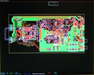
SD-player main PCB is almost completed, I attached a photograph of the CAD design in progress. Component side is in green, solder side in red.
The PCB measures 8.26" (210mm) x 3.93"(100mm). All circuits are integrated, no wiring required. The connectors on the left connect to the front panel PCB. The SD-card holder PCB is mounted on the mainboard using brass hexagonal spacers.
At the right there is the mains adapter socket and a RCA block with 4 sockets, 2 for analogue outputs, one for remote on/off and one for RS232 remote control.
Starting with the power supply, the unregulated mains adapter DC voltage (8 ... 12V) is polarity protected and pre-filtered before feeding the voltage regulators.
Both micros run on 3.3V, this is derived from a 7805 pre-regulator and a 3.3V Micrel ultra low noise regulator. The display driver runs on a separate 7805 and a choke is used for extra filtering.
The DAC chip runs on a discrete LED series regulator with integrated capacitance multiplier. Vref for the DAC chip is generated using cascaded LED shunt regulators with chokes for filtering.
Both master clock and ultra high speed D flip-flop (5-pin SMD) run on 4V constant power regulators consisting of cascaded filters, constant current sources and LED shunt regulators. The clock circuit requires a 2V bias voltage that's also derived from the LED shunt regulators.
The main controller reads the SD-card, outputs I2S, scans the keys, accepts external RS232 commands (remote control), and outputs RS232 commands for the display controller. The display controller drives the LED displays and play indicator LED. LED display colors can be red, orange, yellow, green or blue.
RS232 interfaces have opto-couplers installed for providing galvanic insulation. One is used to drive the display controller, the other for receiving external commands (remote control).
The master clock is a 3-crystal 11.289600 MHz super clock, it consumes approx. 1mA @ 4V (4mW). The crystals run at very low power levels (<1mW). The output signal resembles a pulsed sine wave (looks like a sine wave but has fast positive going transients). The wave form was tuned for most accurate triggering and fewest side bands. The master clock directly drives 2 loads. The master clock is placed in a screened box.
First load is the display controller, the display controller divides the master clock and feeds the main controller. The second load is the ultra high speed D-flip flop that synchronously reclocks BCK from the controller. Signals are injected using additional filters, attenuators and dynamic level shifters.
I2S signals (from the controller) are available on test pins. I2S attenuators (DATA andWS), and dynamic jitter attenuator (BCK) are used to minimize both jitter and interference.
I/V conversion is passive (no active parts), using 2 Beyschlag 1W resistors, two coupling caps and a 3.2V reference voltage. I provided multiple pads on the mainboard for different coupling cap types. Output amplitude equals 1.6Vpp.
Attachments
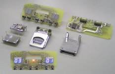
Some more photographs of the completed PCBs:
The display PCB (front and rear side view). The slot is for the SD card PCB.
The SD-card PCB is replaceable, as the SD-card holder is specified for 10,000 card insertions / removals.
The module on the left is the 3-crystal super clock that will be mounted in a screened box later. It can be plugged into the mainboard using special sockets. The master clock design will be modified later, this is just a prototype.
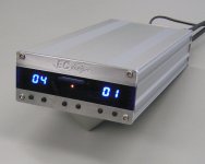
The picture at the bottom shows the front panel being tested. The orange LED indicates play / pause.
The display PCB (front and rear side view). The slot is for the SD card PCB.
The SD-card PCB is replaceable, as the SD-card holder is specified for 10,000 card insertions / removals.
The module on the left is the 3-crystal super clock that will be mounted in a screened box later. It can be plugged into the mainboard using special sockets. The master clock design will be modified later, this is just a prototype.
The picture at the bottom shows the front panel being tested. The orange LED indicates play / pause.
Attachments
Hi John.
Seems that you're making progress.
Perhaps you could think about putting the I/V resistors on stands. This way people
could easily swap the resistors.
My all time favourites are still Rhopoint Econistors.")
BTW. Did you consider the option (extra pins/jumpers) to tap off I2S to allow to feed a different DAC?
Cheers
Seems that you're making progress.
Perhaps you could think about putting the I/V resistors on stands. This way people
could easily swap the resistors.
My all time favourites are still Rhopoint Econistors.
BTW. Did you consider the option (extra pins/jumpers) to tap off I2S to allow to feed a different DAC?
Cheers
Hello EC, now that you are closer to finishing this project did you retain the sound quality you spoke of in the earlier prototypes?
So far you are pretty much right on schedule, but any further details?
I plan to have it ready within a month.
So far you are pretty much right on schedule, but any further details?
Seems that you're making progress.
Well I have been working very hard over the past days. SD-player PCB design was completed, and I manufactured a prototype PCB. I worked till late at night to assemble the PCB, as I couldn't wait to see if it worked as planned.
After assembling all parts, power supplies were tested, so far so good. Next I mounted SD-card holder module and front panel, switched-on and waited ..... nothing.
Turned out to be a short circuit made during soldering the front panel PCB on the SD-player main PCB. After sorting that out, the SD-card wasn't detected ..... forgot a pull-up resistor on the SD-card PCB. Then, for the first time, the SD-player prototype PCB produced sound, but after some time problems occurred (crackling sound). Today that problem was fixed, it was a minor issue with controller power supply decoupling pin that should not have been connected to +3V3.
So it seems I have to perform some minor PCB re-designs only.
After the problems had been sorted out, the new SD-card player prototype was able to outperform the existing prototype setup. Mission accomplished I would say.
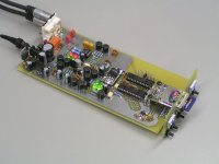
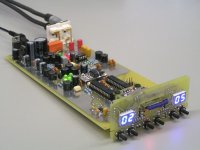
I attached a photograph of the SD-player prototype. As you can see, no wires, all connections are made through the PCBs. This whole unit just slides into the aluminum housing.
The 4 RCA sockets are for audio (L / R), remote power on (orange relay), and RS232 receive input.
The SD-player only consumes approx. 2 Watts now! I used a small external adapter that connects through a DC plug, I set the adapter for approx. 8.5V output voltage. The SD-player power supplies are heavily filtered, and specific voltage regulators were used for each sub-circuit.
The red and green LEDs are part of discrete voltage regulators for DAC chip, master clock and ultra-high speed D flip-flop. The black round parts are 10mH ferrite chokes for filtering. The brown parts are Murata filters with integrated ferrite beads. The 7805 near the DC input drives the display segment buffer only. The second one in the plastic housing is the pre-regulator for the 3V3 Micrel ultra low noise regulator (SMD part near the yellow tantalium cap). The 3V3 regulator drives micros and SD-card.
The two white chips are opto-couplers for RS232 communication. One communication channel is used to drive the display controller, the other accepts external RS232 commands (remote control).
The master clock was further tuned and optimized. The 3 crystals were placed in rubber damping material to minimize the effect of external mechanical vibrations. Wave form was tuned for even steeper positive going transient.
There are only 6 SMD components on the solder side, the microscopic D flip-flop and 5 100nF decoupling caps.
I used a large ground plane for optimal performance. The master clock plugs into the SD-player mainboard using gold-plated sockets. The master clock has the size of a 24-pin IC DIP housing.
Attachments
I attached a photograph of the SD-player prototype. As you can see, no wires, all connections are made through the PCBs.
It will be very difficult to tweak...

Congratulations John.
Best of lucks,
M
PS: anyone interested in a 20kg CDPRO?

PS2: are those Rubycon ZL? I love them...
Congratulations -ecdesigns- !
I have been reading this thread and the one about tda1541, and I am very impressed by the way you have used your knowledge to reveal the shortcomings in existing designs, and now finally presenting a design which seem to be a optimal solution.
Regards
I have been reading this thread and the one about tda1541, and I am very impressed by the way you have used your knowledge to reveal the shortcomings in existing designs, and now finally presenting a design which seem to be a optimal solution.
Regards
A little toy for the waiting period! (only optical output recommended)
TEAC WAP-2200
)TEAC WAP-2200
An externally hosted image should be here but it was not working when we last tested it.
How about using chasis mounted RCA plugs?
Look at the SD-player size, these sockets simply wouldn't fit. Besides, I wouldn't have chosen these RCA socket assemblies if quality wasn't ok.
Will the push buttons too low or the buttons slightly raised.
Well I attached a photograph of the housing that was completed last night, keep in mind that the CNC milled aluminum parts aren't anodized yet.
The front panel consists of two 3mm thick CNC milled aluminum parts. The screws are countersunk and only a small part of the Allen screws sticks out. The logo is engraved (0.5mm deep) in the solid aluminum.
The center part is blue clear perspex, the 3 parts were milled in a way so they interlock.
The orange play / pause LED light is led through a plastic fiber optic that was pressed into the perspex window.
I decided not to add symbols for the keys. The function is logical, the keys underneath each display are for disk / track selection. The remaining two keys are for stop (center left) and start (center right).
The "foot" is just an experiment, these are solid aluminum cones, intended for the sonic resonators that were no longer used. Looks kind of futuristic and makes it very easy to operate the keys and read the display.
The rear panel consists of a CNC milled 2mm thick aluminum plate.
We are also planning to write a software application that runs on all popular platforms, and is tailor made for use with SD-cards and the SD-player. Similar to iTunes it enables managing huge amounts of CDs (WAV format) and greatly simplifies SD-card programming and identification.
Attachments
- Status
- This old topic is closed. If you want to reopen this topic, contact a moderator using the "Report Post" button.
- Home
- Source & Line
- Digital Source
- Lossless SD-card player