Hi John,
As each "floating supply" adds up to a single rail, and needs a complete centre tapped winding each, is it possible to add extra seperate o/p sections from the diodes and "isolating transistors" (the Bds) onwards, so there can be extra parallel floating rails that are also "seperately floating"?
As each "floating supply" adds up to a single rail, and needs a complete centre tapped winding each, is it possible to add extra seperate o/p sections from the diodes and "isolating transistors" (the Bds) onwards, so there can be extra parallel floating rails that are also "seperately floating"?
dddac said:
In that case, why 0,1uF? I would say, space is the limit...
Try farads in parallel with your battery. Car Audio does the same, even though for other reasons as well")
I do have 8*470uf BG in Super-E config running in parallel on my own system.
0.1uf for HF filtering.
Hi soundcheck,
Small (0.1uF) decoupling caps are most effective when placed as close as possible to the load.
I performed some more power supply experiments, compared with a conventional mains power supply, a battery provides superior sound quality, no doubt about that.
Major issues with conventional mains power supplies are 50 ... 120 Hz ripple voltage (mains frequency), and the ac ground loops that are created when feeding multiple interconnected audio devices by mains power supplies.
When the SD-player is running on a battery, and only the power amp is connected to the mains, no ac ground loops can be created as the battery power supply "floats". In other words it's completely isolated from the mains. When connecting only the minus of the Mains adapter, sound degrades significantly, despite the fact that the SD-player still runs on a battery. In this case an ac ground loop is created that runs throug the capacitive coupling between mains adapter primary and secondary transformer windings.
The more interconnected audio devices are being fed by a mains power supply, the worse it will get. This has nothing to do with low ESR but with a mains interference frequency spectrum being super imposed on the circuits of the audio devices.
One way of minimizing ac ground loops is by placing a high impedance between transformer and mains voltage, the mains interference frequency spectrum can be attenuated using multi-stage mains filters that provide very high attenuation. At the same time, these filters can also provide high series impedance.
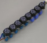
I performed following test, an 8-stage mains filter was constructed using 8 x Schaffner filter chokes, and 9 capacitors.
I attached a photograph of this experimental mains filter. It was placed between the mains adapter and the mains. I also placed some chokes and ferrite beads on the mains adapter DC output. The mains adapter diodes were replaced by Schottky diodes, and the smoothing cap replaced by a 2200uF panasonic FC series cap.
This power supply was then compared with the battery reference power supply by using a DPDT switch that toggled both +12V and GND connections.
Now the mains power supply provides much better results than before, in fact, it even seems to outperform the battery supply.
Back to low ESR, this depends on the application. Low ESR electrolytic caps, used as smoothing caps after the (bridge) rectifier will draw significant peak currents during charging. This in turn will increase mechanical vibrations in the capacitor, the distance between the capacitor plates will now change dynamically, causing capacitance modulation, similar as with condenser microphones:
http://www.mediacollege.com/audio/microphones/condenser.html
because the capacitor is charged, and the distance between the plates changes, unwanted ac voltage is being generated. This noise is super-imposed on the unregulated DC output. The frequency spectrum of this interference signal depends on capacitor mechanical properties (mechanical damping and ESR), the aluminum capacitor housing could even increase the resonance effect.
This unwanted effect can be reduced by placing 0.2 ... 1 Ohm resistors in series with the rectifier diodes, reducing peak charge current and resulting mechanical vibrations inside the smoothing cap.
The same basically happens with coupling caps for audio signals, as these capacitors are charged and a current runs through them and / or are subjected to external mechanical vibration. The best coupling caps for audio may even turn out to be the caps that provide best mechanical damping, and oddly enough this could even depend on the materials used for the capacitor housing, the mechanical properties of the foil, and the free space between the foils.
Here is a link to a capacitor mod that basically affects capacitor mechanical damping properties:
http://www.dhtrob.com/projecten/elna1_en.shtml
I'd recommend to try two or more batteries in parallel (and fully loaded ). Perhaps a small 0,1uf in parallel.
I'd expect even better transients and dynamics. You'll be surprised.
Perhaps you try a 6V batt. This might make the pre-regulation obsolete.
One more: Low ESR is key.
Small (0.1uF) decoupling caps are most effective when placed as close as possible to the load.
I performed some more power supply experiments, compared with a conventional mains power supply, a battery provides superior sound quality, no doubt about that.
Major issues with conventional mains power supplies are 50 ... 120 Hz ripple voltage (mains frequency), and the ac ground loops that are created when feeding multiple interconnected audio devices by mains power supplies.
When the SD-player is running on a battery, and only the power amp is connected to the mains, no ac ground loops can be created as the battery power supply "floats". In other words it's completely isolated from the mains. When connecting only the minus of the Mains adapter, sound degrades significantly, despite the fact that the SD-player still runs on a battery. In this case an ac ground loop is created that runs throug the capacitive coupling between mains adapter primary and secondary transformer windings.
The more interconnected audio devices are being fed by a mains power supply, the worse it will get. This has nothing to do with low ESR but with a mains interference frequency spectrum being super imposed on the circuits of the audio devices.
One way of minimizing ac ground loops is by placing a high impedance between transformer and mains voltage, the mains interference frequency spectrum can be attenuated using multi-stage mains filters that provide very high attenuation. At the same time, these filters can also provide high series impedance.
I performed following test, an 8-stage mains filter was constructed using 8 x Schaffner filter chokes, and 9 capacitors.
I attached a photograph of this experimental mains filter. It was placed between the mains adapter and the mains. I also placed some chokes and ferrite beads on the mains adapter DC output. The mains adapter diodes were replaced by Schottky diodes, and the smoothing cap replaced by a 2200uF panasonic FC series cap.
This power supply was then compared with the battery reference power supply by using a DPDT switch that toggled both +12V and GND connections.
Now the mains power supply provides much better results than before, in fact, it even seems to outperform the battery supply.
Back to low ESR, this depends on the application. Low ESR electrolytic caps, used as smoothing caps after the (bridge) rectifier will draw significant peak currents during charging. This in turn will increase mechanical vibrations in the capacitor, the distance between the capacitor plates will now change dynamically, causing capacitance modulation, similar as with condenser microphones:
http://www.mediacollege.com/audio/microphones/condenser.html
because the capacitor is charged, and the distance between the plates changes, unwanted ac voltage is being generated. This noise is super-imposed on the unregulated DC output. The frequency spectrum of this interference signal depends on capacitor mechanical properties (mechanical damping and ESR), the aluminum capacitor housing could even increase the resonance effect.
This unwanted effect can be reduced by placing 0.2 ... 1 Ohm resistors in series with the rectifier diodes, reducing peak charge current and resulting mechanical vibrations inside the smoothing cap.
The same basically happens with coupling caps for audio signals, as these capacitors are charged and a current runs through them and / or are subjected to external mechanical vibration. The best coupling caps for audio may even turn out to be the caps that provide best mechanical damping, and oddly enough this could even depend on the materials used for the capacitor housing, the mechanical properties of the foil, and the free space between the foils.
Here is a link to a capacitor mod that basically affects capacitor mechanical damping properties:
http://www.dhtrob.com/projecten/elna1_en.shtml
Attachments
Hi jameshillj,
Yes that's possible, but every added floating CT section will increase total stray capacitance (multiple transistors / diodes in parallel). It's also advisable to use suitable mains filtering like the experimental filter in my previous post.
Hi John,
As each "floating supply" adds up to a single rail, and needs a complete centre tapped winding each, is it possible to add extra seperate o/p sections from the diodes and "isolating transistors" (the Bds) onwards, so there can be extra parallel floating rails that are also "seperately floating"?
Yes that's possible, but every added floating CT section will increase total stray capacitance (multiple transistors / diodes in parallel). It's also advisable to use suitable mains filtering like the experimental filter in my previous post.
Hi soundcheck,
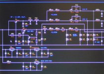
The SD-player needs the following separate power supplies, each with specific properties:
5V series regulator for display segment buffer.
5V series pre regulator for feeding the ultra low noise 3.3V LDO regulator.
3.3V ultra low noise LDO regulator for both processors and SD-card.
5.2V LED-referenced ultra low noise series regulator for feeding DAC chip, I2S attenuators, and Vref circuit.
3.2V cascaded LED shunt regulator for Vref (passive I/V conversion).
4V 80mW ultra low noise constant power regulator for the master clock.
4V 40mW ultra low noise constant power regulator for synchronous reclocker.
2V ultra low noise reference voltage for synchronous reclocker.
When using a 6V battery, there is also too little margin for regulation, I need at least 2 ... 3V margin.
Even when using a battery power supply, separate voltage regulators are still required to isolate sub-circuits (minimize crosstalk between circuits), minimize noise, and provide required specific regulator properties like the constant power regulators.
I attached a screen-shot of the early SD-player voltage regulator schematics to illustrate this.
Perhaps you try a 6V batt. This might make the pre-regulation obsolete.
The SD-player needs the following separate power supplies, each with specific properties:
5V series regulator for display segment buffer.
5V series pre regulator for feeding the ultra low noise 3.3V LDO regulator.
3.3V ultra low noise LDO regulator for both processors and SD-card.
5.2V LED-referenced ultra low noise series regulator for feeding DAC chip, I2S attenuators, and Vref circuit.
3.2V cascaded LED shunt regulator for Vref (passive I/V conversion).
4V 80mW ultra low noise constant power regulator for the master clock.
4V 40mW ultra low noise constant power regulator for synchronous reclocker.
2V ultra low noise reference voltage for synchronous reclocker.
When using a 6V battery, there is also too little margin for regulation, I need at least 2 ... 3V margin.
Even when using a battery power supply, separate voltage regulators are still required to isolate sub-circuits (minimize crosstalk between circuits), minimize noise, and provide required specific regulator properties like the constant power regulators.
I attached a screen-shot of the early SD-player voltage regulator schematics to illustrate this.
Attachments
Hi John.
1. ESR makes a huge difference. I compared different batteries. Any mR on the power rail makes a difference. The slew rate on the power rail is IMO one of the key issues to look at.
Check also Paul Hynes PS. He is pretty much focussing on low ESR and high Slew rates
nowadays.
2. 0,1 u+8*470uf: My buffer sits right in front of the DAC
3. Main filters come with a lot of negative side effects. They usually slow down the traffic.
4. A big issue is DC on the power rail. You need to filter that one out first. (It won't be done by
the Schaffners) Otherwise all transformers will perform much worse. The pity -- even your
house distribution frame, will act like a filter, causing problems.
5. Coupling caps: I use special Mica caps from Thel-Audioworld on my amp input. These
have extremely low vibrations. They sound cristal clear.
6. Perhaps you try another battery: http://www.panasonic.com/industrial/battery/oem/images/pdf/Panasonic_VRLA_LC-X1228P_LC-X1228AP.pdf . 2 of them in parallel and a low esr buffer.
Cheers
Hi ccschua,
I settled for 5.2V DAC chip power supply. This voltage provided best sonic performance while using a virtually perfect digital audio source.
Increased DAC power supply voltage will increase on-chip ground bounce and as a result of this increases sample timing jitter.
The chip temperature will increase, making it difficult or even impossible to maintain optimal / stable chip temperature for highest accuracy (current reference sources, bias current sources, current dividers).
There is also no practical need to increase DAC power supply voltage (5.2V) as output amplitude is only 1.5Vpp.
Lowering DAC power supply voltage would decrease ground-bounce, but would also affect accuracy (chip operating temperature).
The DAC chip performs best after a warming-up period of 10 ... 15 minutes, after this time the chip temperature has settled, and the analogue circuits provide highest accuracy.
will the sound improve if the Vcc is 8V instead of 5V ?
I settled for 5.2V DAC chip power supply. This voltage provided best sonic performance while using a virtually perfect digital audio source.
Increased DAC power supply voltage will increase on-chip ground bounce and as a result of this increases sample timing jitter.
The chip temperature will increase, making it difficult or even impossible to maintain optimal / stable chip temperature for highest accuracy (current reference sources, bias current sources, current dividers).
There is also no practical need to increase DAC power supply voltage (5.2V) as output amplitude is only 1.5Vpp.
Lowering DAC power supply voltage would decrease ground-bounce, but would also affect accuracy (chip operating temperature).
The DAC chip performs best after a warming-up period of 10 ... 15 minutes, after this time the chip temperature has settled, and the analogue circuits provide highest accuracy.
Hi nicoch46,
These are sealed, valve-regulated lead acid batteries. The Sulfuric acid is usually bound in a gel, so even when the battery breaks, there is no spillage and the battery continues to function. Since the battery is hermetically sealed (under normal operating conditions) it won't release Hydrogen nor Oxygen either. So yes, this type of battery is safe.
this type of battery are safe ?
ie. don't put out acid gas ?
These are sealed, valve-regulated lead acid batteries. The Sulfuric acid is usually bound in a gel, so even when the battery breaks, there is no spillage and the battery continues to function. Since the battery is hermetically sealed (under normal operating conditions) it won't release Hydrogen nor Oxygen either. So yes, this type of battery is safe.
by pass capacitors with battery
Is the work done many years ago in l'Audiophile by Guy Marec still valid ?
The conclusion was that you need huge (>200.000 uf) caps with low esr to get the best results with battery. In fact he got really good results without battery using a current source and a shung reg accros the huge caps.
Best regards.
Philippe.
DC generator test - zero coupling capacitance
Hi plep,
When using conventional mains power supplies, there is always the coupling capacitance between both primary and secondary transformer windings. No regulator or smoothing cap can do anything about this, and the related effects on sound quality remain.
What basically happens is that both GND and plus are connected directly to the polluted mains voltage by a capacitor (coupling capacitance between transformer primary and secondary windings). This impedance is low enough to pass unwanted HF interference between interconnected mains-powered audio equipment.
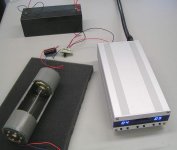
Yesterday I did an interesting experiment. I attempted to completely eliminate this coupling capacitance by using a small DC motor / generator combination. I used 2 identical 12V DC motors, one is used as motor, the other as generator.
The motor was fed by a small mains adapter, both motor and generator were mounted in a plastic tube (insulator). Both motor and generator axes were coupled by using a 7 cm long clear plastic tube (insulator). This creates an approx. 6 cm wide insulated barrier between both motor and generator metal parts (axis inclusive), obtaining virtually zero coupling capacitance between both mains adapter and connected load.
The generator output only needs to be smoothened a bit using a 1000uF electrolytic capacitor, note that the polarity is reversed (red wire minus, blue wire plus). No rectifier diodes are needed as the generator has a collector. The motor red wire is connected to plus, the blue wire to minus of the 12V mains adapter.
The motor / generator combination very closely matched two fully charged twin lead-acid batteries in parallel !
This experiment basically shows that the capacitive coupling with the mains (conventional mains power supplies) is quite problematic for audiophile equipment sound quality.
I attached a photograph of this test setup, In this picture, the switch connects the generator to the SD-player.
Hi plep,
The conclusion was that you need huge (>200.000 uf) caps with low esr to get the best results with battery. In fact he got really good results without battery using a current source and a shung reg accros the huge caps.
When using conventional mains power supplies, there is always the coupling capacitance between both primary and secondary transformer windings. No regulator or smoothing cap can do anything about this, and the related effects on sound quality remain.
What basically happens is that both GND and plus are connected directly to the polluted mains voltage by a capacitor (coupling capacitance between transformer primary and secondary windings). This impedance is low enough to pass unwanted HF interference between interconnected mains-powered audio equipment.
Yesterday I did an interesting experiment. I attempted to completely eliminate this coupling capacitance by using a small DC motor / generator combination. I used 2 identical 12V DC motors, one is used as motor, the other as generator.
The motor was fed by a small mains adapter, both motor and generator were mounted in a plastic tube (insulator). Both motor and generator axes were coupled by using a 7 cm long clear plastic tube (insulator). This creates an approx. 6 cm wide insulated barrier between both motor and generator metal parts (axis inclusive), obtaining virtually zero coupling capacitance between both mains adapter and connected load.
The generator output only needs to be smoothened a bit using a 1000uF electrolytic capacitor, note that the polarity is reversed (red wire minus, blue wire plus). No rectifier diodes are needed as the generator has a collector. The motor red wire is connected to plus, the blue wire to minus of the 12V mains adapter.
The motor / generator combination very closely matched two fully charged twin lead-acid batteries in parallel !
This experiment basically shows that the capacitive coupling with the mains (conventional mains power supplies) is quite problematic for audiophile equipment sound quality.
I attached a photograph of this test setup, In this picture, the switch connects the generator to the SD-player.
Attachments
HI
I made a little research on battery charger ,for small battery the Optimate SP III is very good if not the best......
for normal use car/moto 50Ah the Optimate 4
http://www.tecmate-int.com/
I made a little research on battery charger ,for small battery the Optimate SP III is very good if not the best......
for normal use car/moto 50Ah the Optimate 4
http://www.tecmate-int.com/
Hi EC,
So, in that aspect it is better to use R core or similar transformer, right? ...as primary and secondary windings are separated... (I mean C core; EI...)
When using conventional mains power supplies, there is always the coupling capacitance between both primary and secondary transformer windings. No regulator or smoothing cap can do anything about this, and the related effects on sound quality remain.
So, in that aspect it is better to use R core or similar transformer, right? ...as primary and secondary windings are separated... (I mean C core; EI...)
Hi maxlorenz,
Separating the windings doesn't mean that there is no coupling capacitance between both windings. First the windings are located side by side, creating a capacitance between both. Each winding also sits on an iron core, creating a capacitance between winding and this iron core material.
The end effect is that you have two capacitances in series (primary - core - secondary), and one more in parallel (primary - secondary). The capacitance is formed by the copper masses in both windings, coil formers, and iron core material. The other capacitance is formed by the copper masses of both windings and insulation between these.
In practice the coupling capacitance (depending on transformer properties) can vary between a few hundred pF up to a few nF.
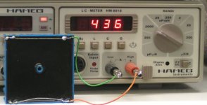
This capacitance can be measured by short-circuiting all primary winding contacts, and shorting all secondary winding contacts (no short circuit between primary and secondary). Now connect a capacitance meter between both the primary and secondary connections. I use a Hameg LC meter for this purpose. I attached a photograph showing the capacitance between both primary and secondary windings of a toroidal transformer, reading is in pF, so this transformer has approx. 436 pF between both primary and secondary windings.
The motor / generator configuration has a 6 cm gap (plastic insulator) between both motors, and the surface area of the metal parts that are closest together is very small (thin axis). In order to achieve similar with a transformer, one would need an air gap of over 10 cm!
When doing so, the transformer will no longer function, the impedance goes down, and efficiency would be very low.
As far as I know, it's not possible to achieve zero coupling capacitance, using regular mains transformers, regardless of type and brand. In practice the coupling capacitance must be virtually zero in order to match battery power supply (floating power supply) performance.
The floating CT supply can reduce coupling capacitance to a few pF, and does improve things, but semiconductor properties (capacitance) still prevent required zero coupling capacitance.
The trick is to construct a mains power supply that has virtually zero coupling capacitance, one practical application that works is the motor-generator configuration. I am still trying to figure out a way that doesn't require moving parts. Until then, the battery power supply is the most practical option.
So, in that aspect it is better to use R core or similar transformer, right? ...as primary and secondary windings are separated... (I mean C core; EI...)
Separating the windings doesn't mean that there is no coupling capacitance between both windings. First the windings are located side by side, creating a capacitance between both. Each winding also sits on an iron core, creating a capacitance between winding and this iron core material.
The end effect is that you have two capacitances in series (primary - core - secondary), and one more in parallel (primary - secondary). The capacitance is formed by the copper masses in both windings, coil formers, and iron core material. The other capacitance is formed by the copper masses of both windings and insulation between these.
In practice the coupling capacitance (depending on transformer properties) can vary between a few hundred pF up to a few nF.
This capacitance can be measured by short-circuiting all primary winding contacts, and shorting all secondary winding contacts (no short circuit between primary and secondary). Now connect a capacitance meter between both the primary and secondary connections. I use a Hameg LC meter for this purpose. I attached a photograph showing the capacitance between both primary and secondary windings of a toroidal transformer, reading is in pF, so this transformer has approx. 436 pF between both primary and secondary windings.
The motor / generator configuration has a 6 cm gap (plastic insulator) between both motors, and the surface area of the metal parts that are closest together is very small (thin axis). In order to achieve similar with a transformer, one would need an air gap of over 10 cm!
When doing so, the transformer will no longer function, the impedance goes down, and efficiency would be very low.
As far as I know, it's not possible to achieve zero coupling capacitance, using regular mains transformers, regardless of type and brand. In practice the coupling capacitance must be virtually zero in order to match battery power supply (floating power supply) performance.
The floating CT supply can reduce coupling capacitance to a few pF, and does improve things, but semiconductor properties (capacitance) still prevent required zero coupling capacitance.
The trick is to construct a mains power supply that has virtually zero coupling capacitance, one practical application that works is the motor-generator configuration. I am still trying to figure out a way that doesn't require moving parts. Until then, the battery power supply is the most practical option.
Attachments
Hi Ecdesigns,
I forgot to say that Guy Marec used an Xforner with 2 shields (input and output), wich seems rather uncommon these days.
What I was refering was the use of high value caps tu reduce and linearise bettery impedance. It was concidered much better than classical regulators. But then you are rigth, coupled to the mains...
Your idea of motor + generator is interessting, at the least. You probably can change the frequency of the "main" as well.
Best regards.
Philippe.
Please keep it simple!
I am not sure but I am in doubt that anyone can really hear the difference between a well made mains supply and battery. I tried 5 eneloops with my TDA1543 DAC and found the cheap wallwart equal.
I know it is DIY and exotic solutions are welcome to get the last percent but today I don't want to live with too much compromises. And lead batteries aren't a solution for me to feel relaxed.
photovoltaic cell
you can try using photovoltaic cell.
place it in the sun for a green solution.
put an array of mains powered leds over it for a reliable output.
i hope the abyssmal efficiency and costs are worth while. hahaha.
at least it is silent . . .
good thing tt the player does not consume too much juice.
and superb work there EC!
xianyang
- Status
- This old topic is closed. If you want to reopen this topic, contact a moderator using the "Report Post" button.
- Home
- Source & Line
- Digital Source
- Lossless SD-card player