bear said:
Ok. maybe I need to read about the LT some more... perhaps I missed something? Hmmm... citations, URLs that make the case?
The LT can't be another hammer, except in a situation where we are looking at a semi or actually steady state excitation.
The input "transform" no matter what it is set to do has no way to keep track of the response of the speaker without closing the feedback loop, in which case I would agree that the response of the system can be altered within the bounds of the ability of the motor to control the cone (and even there, not quite perfectly)...
[snip]
Show me any filter circuit that can correct the impulse response of a speaker so that it is just that little spike and nothing more, and I will show you some fairy tale books. No input filter can change the stored energy in a given driver/speaker system.
_-_-bear
(JPK) The LT is of course a different hammer. Suppose you have a sealed box with Q = 5 at fs = 100 Hz and you want Q=0.7 at 50 Hz. What does the Q=5, fs 100 response look like in steady state? What about to an impulse or step? We all know the answer. And we know what the response of a Q = 0.7, fs = 50 Hz system looks like. So what do we need for the LT? Let TF(Q=5) be the transfer function of the original system and TF(Q=0.7) the target. The TF(LT) = TF(Q=0.7)/TF(Q=5). Obviously the LT response to a step or impulse is different from the input, a different hammer. There is no need for feedback. There is no need to track the driver's response. We already know it's TF(Q=5) so if the LT is defined as noted above the resulting output will be TF(Q=0.7) under steady or transient conditions unless for some reason (nonlinearity) the original response deviates from TF(Q=5). But such deviartion occurs whether the system is tranformed or not. That is, knowing the linear behavior of the original system we can correct it to behave as a different linear system. What we can not correct is for potential nonlinearities.
Stored energy is a linear phenominon and easily corrected for by linear corrections.
Here let me postulate a simple experiment. Suppose we build the system above, un LT'ed Q = 5, Fs = 100Hz, with LT, Q=0.7, Fs = 50 Hz. Now I set this up to measure. SO it stick a mic near the dust cap and run a sine sweep and then an MLS measurement. Both will yield the same thing, a steady state frequency response of a Q = 5, fs = 100 Hz system. Now I put the LT in place. I run the same two measurements. You are saying that the sine sweep would yield the correct, Q=0.7, fs = 50 Hz response but the MLS measurement would yield something else because the LT'ed response could not possible give the right impulse response for a Q=0.7 fs 50Hz system here and the MLS measurement reduces to the system impulse response. I.e, it's a time domain measurement. I think it's pretty clear to most here that the MLS measurement will, however, yield the correct Q=0.7, fs = 50 hz response.
We should leave this where it is pretty much.
It's obvious that if you can correct the impulse response so that it looks the same as the impulse response of a target then the result is the same.
We only differ on the practical implementation - to wit that the speaker cone will cooperate with the electrical "instruction" in the absence of feedback. I feel you're optimistic about that in the examples we're using...
_-_-bear
Konnichiwa,
IN THEORY, yes.
In practice drive units fundamental parameters (and thus the derived TS Parameters) vary between different samples AS WELL as with signal, therefore making a reliable "feed forward" style compensation at the very least difficult.
I would suggest you consider solving the problem of damping a mechanical resonance using mechanical means, which will be a much superior and reliable solution.
Sayonara
454Casull said:Could it be fixed with something as simple as a Linkwitz transform?
IN THEORY, yes.
In practice drive units fundamental parameters (and thus the derived TS Parameters) vary between different samples AS WELL as with signal, therefore making a reliable "feed forward" style compensation at the very least difficult.
I would suggest you consider solving the problem of damping a mechanical resonance using mechanical means, which will be a much superior and reliable solution.
Sayonara
Would a lower DC resistance of the voice coil improve damping?
Not at all, since its effect on damping is eliminated by the use of current drive.
An intermedite solution might not be bad: An amp with a higher than normal output resistance, that has still some control over electrical damping. I assume that this will be less susceptible to mechanical variations but will still leave us with some advantages of current drive. I assume that even Thorsten's (who seem to really dislike electrical damping) Supravox is driven by an amp that more or less represents a voltage source, isn't it ?
Regards
Charles
Sorry I was refering to a lower DC resistance in a voltage drive application. I think that would improve damping in a voltage drive system, but would have no effect on a current drive.
I think a carefull analysis will show that any attempt to modify a current drive signal to improve damping will result in a signal to the speaker that is the same as a voltage drive.
The only ways to mechanically dampen that I know of are an "eddy brake" (those copper "shorting rings") that many drivers have, or a lossy suspension.
Loss of electrical damping for bass drivers powered by current drive
Could it be fixed with something as simple as a Linkwitz transform?
Instead of being helpful, I'll reject the premise.
Others have already hinted at it: If you need a complicated network to compensate for behavior introduced by current drive, then don't use current drive.
I see current drive as primarily a response-shaping tool. If it's lower dynamic compression you're after, then consider that any driver that can stand up long-term under the additional VC heating of current drive already probably has little dynamic compression. From another angle: if you're driving a given driver's VC to the point that its Re is changing significantly, then don't dump more heat into it, upgrade.
The great thing about higher amp output impedence, as I see it, is that applying varying degrees of Zout can magically tranform a low-Q, high-BL, high-efficiency prosound driver, one that was only good for horns or reflex, into a fantastic choice for sealed and velocity-principle alignments.
It lets you pile on just about all the motor strength and mechanical cone damping you want without having to kiss your bass goodbye.
Konnichiwa,
The Supravox is designed for voltage drive, as are most other modern Drivers. So I drive it as designed, it would not work too well otherwise....
Sayonara
phase_accurate said:I assume that even Thorsten's (who seem to really dislike electrical damping) Supravox is driven by an amp that more or less represents a voltage source, isn't it ?
The Supravox is designed for voltage drive, as are most other modern Drivers. So I drive it as designed, it would not work too well otherwise....
Sayonara
Konnichiwa,
Depends. If you use negative feedback to suppress the resonance the results will be more interesting....
You must account for the whole Driver/Enclosure system. There are many ways to make a highly dampoing enclosure. But it helps if the Driver has a fairly low Qm, many excellent sounding seas ones do.
However, using a seamless conductive voicecoil fromer strikes me as IDEAL. Even better if the voicecoil former can be made magnetic, in which case it can substitute the rear centering spider or other centering device.
It does mean to design a driver explicity for current driver with a Qm equal to the desired Qt of the driver and one should still try making the magnet field as linear as can be....
Sayonara
hummhoom said:I think a carefull analysis will show that any attempt to modify a current drive signal to improve damping will result in a signal to the speaker that is the same as a voltage drive.
Depends. If you use negative feedback to suppress the resonance the results will be more interesting....
hummhoom said:The only ways to mechanically dampen that I know of are an "eddy brake" (those copper "shorting rings") that many drivers have, or a lossy suspension.
You must account for the whole Driver/Enclosure system. There are many ways to make a highly dampoing enclosure. But it helps if the Driver has a fairly low Qm, many excellent sounding seas ones do.
However, using a seamless conductive voicecoil fromer strikes me as IDEAL. Even better if the voicecoil former can be made magnetic, in which case it can substitute the rear centering spider or other centering device.
It does mean to design a driver explicity for current driver with a Qm equal to the desired Qt of the driver and one should still try making the magnet field as linear as can be....
Sayonara
Even a driver with highly linear magnetic field won't exhibit linear behavior. The force generated by a voice coil is not only non-linear with respect to position, but also with respect to current.
I have to agree will Bill that things are just stacked against current drive.
I was almost going to start a new thread on current -vs- voltage drive once I sawwhere this on was going.
I have to agree will Bill that things are just stacked against current drive.
- What's the difference between current drive and voltage drive if you're using positional feedback or a linkwitz transform to change the response anyways? Voltage drive is a tried and true method.
- More power will be dumped into the driver as it heats up, exacerbating the problem. If the voice coil is heating so much that its resistance changes enough to be audible, you probably need a little more speaker to handle the power.
- One little odity with current drive is that power will incease with increasing impedance, rather than decrease as with voltage drive. People will stop bragging about 100,000uF power supplies and start bragging about 200V power supplies. Wait 'til somebody comes out with an amplifier claiming 16-ohm capable.
I was almost going to start a new thread on current -vs- voltage drive once I sawwhere this on was going.
However, using a seamless conductive voicecoil fromer strikes me as IDEAL. Even better if the voicecoil former can be made magnetic, in which case it can substitute the rear centering spider or other centering device.
Yeah, I've given this some thought as I've tried to imagine a no-compromise current-driven wideband. I believe one problem with a seamless conductive former, however, is that it will cause a roll-off with increasing frequency as it couples with AC in the coil.
One workaround might be simply to put eddy-brake rings outboard of an underhung VC on a nonconductive former.
Or you could put the inductive coupling to work for you by attaching at least part of the VC winding to a gap face to inductively drive your eddy brake--just riffing out loud here...
Also, I agree that magnetic suspensions are a great idea, but a conductive ferromagnetic eddy brake is bound to exhibit some hysteresis--though perhaps not prohibitively so.
Konnichiwa,
Actually, that is not entierly exact. Assuming a completely homogenous magnetic field the force generated by the voicecoil is PURELY AND TOTALLY determined by the current following an equation without any non-linear components. It is the Voltage Drive option which is inherently nonlinear due to the iron pole pieces.
They are? I did not notice.
hummhoom said:Even a driver with highly linear magnetic field won't exhibit linear behavior. The force generated by a voice coil is not only non-linear with respect to position, but also with respect to current.
Actually, that is not entierly exact. Assuming a completely homogenous magnetic field the force generated by the voicecoil is PURELY AND TOTALLY determined by the current following an equation without any non-linear components. It is the Voltage Drive option which is inherently nonlinear due to the iron pole pieces.
hummhoom said:I have to agree will Bill that things are just stacked against current drive.
They are? I did not notice.
hummhoom said:
- What's the difference between current drive and voltage drive if you're using positional feedback or a linkwitz transform to change the response anyways? Voltage drive is a tried and true method.
Hmmm. The differences are quite large. Voltage drive, in real drivers adds a cubic distortion function which is independent from frequency and generaly rises to middle frequencies where the ear becomes more sensitive. Positional feedback will reduce distortion, LWT will not, nor is LWT sufficiently reliable when large changes of Q and Fs are attempted.
hummhoom said:[*]More power will be dumped into the driver as it heats up, exacerbating the problem. If the voice coil is heating so much that its resistance changes enough to be audible, you probably need a little more speaker to handle the power.
??? So, you mean to say the compression when using voltage drive which is around 1db at 1W for many "HiFi" Drivers and as much as 6db at rated power (figures from a Studio Sound Test of Monitors vs HiFi Speakers) together with a complex slow "release" and "fast attack" envelope function is a good thing to have???
hummhoom said:[*]One little odity with current drive is that power will incease with increasing impedance, rather than decrease as with voltage drive.
Which coincidentally (actually, incidentally as I always say - Coincidences aren't) also largely happens where normally drive units roll off their acoustic output!
hummhoom said:I was almost going to start a new thread on current -vs- voltage drive once I sawwhere this on was going.
Before you start such a thread, note that at the beginning of any new thread there is a checkbox that asks: "Have you searched?". You may wish to do that, as all this ground has been extensively covered before. It might also help to get facts straight, which is always a useful thing is discourse and discussion.
Sayonara
I have to agree will Bill that things are just stacked against current drive.
Just to clarify my position on current drive —
In a nutshell: Don't throw out current drive--it's wonderful. Throw out your weak-motored mid-Q drivers, buy some brawny, highly-damped low-Q drivers, and add Zout to taste.

Kuei Yang Wang said:
Actually, that is not entierly exact. Assuming a completely homogenous magnetic field the force generated by the voicecoil is PURELY AND TOTALLY determined by the current following an equation without any non-linear components. It is the Voltage Drive option which is inherently nonlinear due to the iron pole pieces.
You're forgetting about voice coil reaction. It's different from reactance. The current in the voice coil creates a magnetic field of it's own that distorts the magnetic field it operates in. I guess it's more of a concern with weaker motors. A lot of non linearity blamed on the magnetic structure is really reaction. The strong part of the magnetic field is fairly short, while the effective length of the voice coil is long in comparison. Non linear motor behavior occurs long before the excursion is high enough to be associated with a non linear magnetic structure.
Konnichiwa,
NO I AM NOT. I am eliminating it as a problem by "fixing" the current through the voice coil.
PLEASE, first study the material extant on the topic and then previous discussion, all this has been covered so many times.
Sayonara
hummhoom said:You're forgetting about voice coil reaction.
NO I AM NOT. I am eliminating it as a problem by "fixing" the current through the voice coil.
PLEASE, first study the material extant on the topic and then previous discussion, all this has been covered so many times.
Sayonara
...iirc, the original Lowthers or Voights used no rear spider assembly and had some sort of magnetic centering set up in place using the VC...
...and are we saying that "current amplification" is going to be different than putting a resistor in series with my big *** voltage amplifier? (big *** to assure sufficient swing to reach the same SPLs...)
...and does my "current amplifier" sit at a fixed output voltage and vary current with respect to the input signal? Curious about that point...
... do we have a schematic of a proposed pure "current" amplifier for audio? (there are some damn fast current op amps...)
just thinking out loud...
_-_-bear
Konnichiwa,
Well, the bottom line would be that it is basically the same as putting a WHOPPING BIG (infinite value in theory) after your WHOPPING BIG (in theory infinite voltage) Amp.
No, it ignores the output voltage completely and causes in the load a current to flow that is proportionally to the input signal and only to it.
There are so many options, using either NFB or not to accomplish the job defined above as "It causes in the load a current to flow that is proportionally to the input signal and only to it." that it can be left to devices of the well understanding designer to work out which methode he prefers.
I would propose a penthode with unbypassed cathode resistor (this reduces transconductance but makes it more linear) in SE Class A.
Sayonara
bear said:...and are we saying that "current amplification" is going to be different than putting a resistor in series with my big *** voltage amplifier? (big *** to assure sufficient swing to reach the same SPLs...)
Well, the bottom line would be that it is basically the same as putting a WHOPPING BIG (infinite value in theory) after your WHOPPING BIG (in theory infinite voltage) Amp.
bear said:...and does my "current amplifier" sit at a fixed output voltage and vary current with respect to the input signal? Curious about that point...
No, it ignores the output voltage completely and causes in the load a current to flow that is proportionally to the input signal and only to it.
bear said:... do we have a schematic of a proposed pure "current" amplifier for audio? (there are some damn fast current op amps...)
There are so many options, using either NFB or not to accomplish the job defined above as "It causes in the load a current to flow that is proportionally to the input signal and only to it." that it can be left to devices of the well understanding designer to work out which methode he prefers.
I would propose a penthode with unbypassed cathode resistor (this reduces transconductance but makes it more linear) in SE Class A.
Sayonara
If the amp were capable of providing enough voltage swing then the end result would be identical. It's just not practical because of power losses.bear said:...and are we saying that "current amplification" is going to be different than putting a resistor in series with my big *** voltage amplifier? (big *** to assure sufficient swing to reach the same SPLs...)
A current amplifier will provide whatever output voltage is required to cause the correct current to flow. This is equivalent to a voltage amplifier which will provide whatever current is needed to cause the correct voltage at the output.bear said:...and does my "current amplifier" sit at a fixed output voltage and vary current with respect to the input signal? Curious about that point...
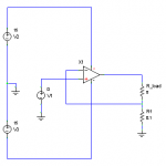
I've attached a rough schematic of a pure current amplifier. Feedback is taken in series with the output via a resistor instead of in parallel like a voltage amp. It is possible to mix current and voltage feedback to acheive specific output impedances.bear said:... do we have a schematic of a proposed pure "current" amplifier for audio?..
This is a point which causes much confusion. Current feedback as used in relation to op-amps means that the feedback node is low impedance, so the feedback signal is injected as a current with the feedback node sitting at a constant voltage. Current feedback as everyone else uses it means that the feedback signal is proportional to the output current, otherwise known as series derived feedback.bear said:...there are some damn fast current op amps....
Attachments
- Status
- This old topic is closed. If you want to reopen this topic, contact a moderator using the "Report Post" button.
- Home
- Loudspeakers
- Multi-Way
- Loss of electrical damping for bass drivers powered by current drive