It's been about 15 years ever since i have been infected with the electronics virus and in all that time i don't think i've met anyone quite like you @lazzer408, maybe that says it all..
You keep asking about the best that, the highest other and blame us for arguing about the power output when in fac we should unswear youre question, but you stubbornly do not got it that in normal calss of opperation AB no matter what IC you use the power cannot be more that 10W SE and 20W BTL, so it really does not matter what IC you choose, they all do the same thing, they all have the same maximum possible power so you choose whatever you want, as @theAnonymous1 says, i give up and you can learn about the bassics of audio electronics ( of wich you have absolutely no ideea ) from books of whatever source you like, fact is you need it.
Good luck.
Why are some rated at 14.4v 5w or 7w or 10w? I'd guess anything lower then 10w may just have a lower fixed gain? Do you know of any simple 20x20x20w BTL ICs?
I've been 'infected' since age 5 but the only audio amp I've built from scratch was tubed unless you consider a 144kw motor controller an amp. I did slap together a TDA1517 yesterday as my first IC amp. Sounds ok but there's not much to the design. 5 caps, the IC, and a stereo pot. Impressive for it's size though.
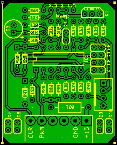
I have a very large understanding of electronics for someone who's never taken classes on it. I've built alot of things. Here's a pic of my board layout for a quad comparator based PWM front end (to the motor controller I mentioned) FROM SCRATCH. Has oscillator, PWM comparator, throttle buffer, open throttle shutdown, throttle ramp, power-up throttle disable if >5%, and current limiter all out of one quad comparator. All off self-taught knowledge.
Please don't belittle my understanding of electronics just because I didn't immediately grasp the concept of an SE audio IC's output swing.
I've been 'infected' since age 5 but the only audio amp I've built from scratch was tubed unless you consider a 144kw motor controller an amp. I did slap together a TDA1517 yesterday as my first IC amp. Sounds ok but there's not much to the design. 5 caps, the IC, and a stereo pot. Impressive for it's size though.
I have a very large understanding of electronics for someone who's never taken classes on it. I've built alot of things. Here's a pic of my board layout for a quad comparator based PWM front end (to the motor controller I mentioned) FROM SCRATCH. Has oscillator, PWM comparator, throttle buffer, open throttle shutdown, throttle ramp, power-up throttle disable if >5%, and current limiter all out of one quad comparator. All off self-taught knowledge.
Please don't belittle my understanding of electronics just because I didn't immediately grasp the concept of an SE audio IC's output swing.
Attachments
Last edited:
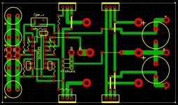
SMPS units are not that easy to built and even harder to desighn, there are many variables that can go wrong or contribute to bad results, and as i see your desighn still needs work, and maybe you need more studdying on this matter, but here is a suggestion for a SMPS unit desighned by me, maybe it will help you.
Attachments
Since I don't consider myself an audiophile (can't afford to be), and it's for a motorcycle, I can leave out quite a few things that one might normally find in a quality SMPS like proper filtering, proper gate drive, regulated vcc, ect. The gates should at least have some 100k or so to ground to keep them off should the PWM IC fail. I won't hear any noise it may create anyway. It will get the job done if I can build it on perfboard.That's why the layout is fairly "squarish". I couldn't etch a PCB to save my life.  I don't know where to find xformers either. I'll just wind my own.
As far as PWM goes, I've made many motor controllers that worked well. When you have 120v@500a you can't afford to screw it up.
Why did you choose to use a totem over a driver IC? Also, I don't see current limiting or voltage regulation. Didn't need it?
I also have my IC mislabled as a 3525. It's a 3524. I already know I have gate drive issues. -doh-
I don't know where to find xformers either. I'll just wind my own.As far as PWM goes, I've made many motor controllers that worked well. When you have 120v@500a you can't afford to screw it up.
Why did you choose to use a totem over a driver IC? Also, I don't see current limiting or voltage regulation. Didn't need it?
I also have my IC mislabled as a 3525. It's a 3524. I already know I have gate drive issues. -doh-
Last edited:
Are you talking about my desighn here?...The gates should at least have some 100k or so to ground to keep them off should the PWM IC fail....
PS; Stop editing your post ( u're not making much sense ) and answear my question here.
Last edited:
- Status
- This old topic is closed. If you want to reopen this topic, contact a moderator using the "Report Post" button.
- Home
- Amplifiers
- Chip Amps
- Looking for the right IC for an amp project.