I have build dual mono amps with balanced inputs (symetrical source was mendatory). But have not found it to be an advantage after all . Too complex to troubleshoot in case something went bad. Also hum can be an issue as the power supply was not stabilized in my case and the amps wander off…
I use a balanced input for each channel, and each phase of the input drives a single-ended output stage.
So I can test each stage with a single ended signal if need be.
I understand the need for simple and quick troubleshooting of these animals - I maintain a prototype amp with power supply on my bench just in case.
On a demo evening at an audio club two weeks ago one amp slid off the chair and crashed on the floor.
One broken tube was all. Trouble shooting, replace tube and retest all in less than half an hour.
Jan
Attachments

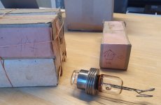
Pulled the trigger and ordered a handful of GI-17 tubes from retrostore.eu, at a very good price.
They are equivalent to CV-1256 family.
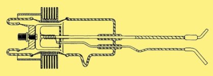
Interesting (for me) that the C and heater are interconnected but the heater is indirect.
When they arrive, I will set up a test circuit and report back here.
I will also have to find a way to mount them.
Jan
They are equivalent to CV-1256 family.
Interesting (for me) that the C and heater are interconnected but the heater is indirect.
When they arrive, I will set up a test circuit and report back here.
I will also have to find a way to mount them.
Jan
Attachments
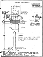
Here is info about mounting of these micropups:
http://www.r-type.org/exhib/acf0117.htm
Looks a bit challenging.
http://www.r-type.org/exhib/acf0117.htm
Looks a bit challenging.
Yes needs some thought. The grid thread is #0BA which is like metric M6 but with wider pitch of 1mm, but material is available if you look.
I have a vague idea about some sort of plug-in module with the heater smps and and a small whisper fan.
Sould be interesting, I love such a challenge!
Keep the ideas coming!
Jan
I have a vague idea about some sort of plug-in module with the heater smps and and a small whisper fan.
Sould be interesting, I love such a challenge!
Keep the ideas coming!
Jan
In the data sheet they specify air flow on the anode as well as on the grid seal.
But that's 'just' mechanics.
I also wonder how much the requirements can be relaxed when Pa is 40W instread of 150W.
Heater power is almost as much.
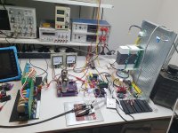
The thermal camera will be broken out. 140deg C is max.
Jan
But that's 'just' mechanics.
I also wonder how much the requirements can be relaxed when Pa is 40W instread of 150W.
Heater power is almost as much.
The thermal camera will be broken out. 140deg C is max.
Jan
Friends, any Russian speaker can translate the main data from the attached? For instance, is Gm 12mA/V (line 3)?
I take it that Vf should be between 5.7 and 6.9V, but what's If?
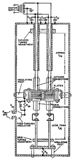
(Also found a nice clear drawing of the internal construction).
Jan
I take it that Vf should be between 5.7 and 6.9V, but what's If?
(Also found a nice clear drawing of the internal construction).
Jan
Attachments
Last edited:
That's it, cetka is grid,
so Uc is Vg
I think you already guessed that
B stands for V(olt)
kB fo kV
BT for Watt.
Obviously main application was generation of RF pulses, radar maybe ...
The table gives only 2 characteristic points:
Va = Vg = 1050 Volt ---> at least 70 Amps
Va = 4 kVolt / Vg = - 900 Volt ---> no more than 5 mA (cutoff)
The next line seems to contain a typo, Va should read Vg, and the 2 uA max
is the max grid current at Vg = -250 Volt / Ia = 0.2 A.
Your data sheet also gives
max anode dissipation: 150 Watt
max. anode voltage: 9 kV
max frequency 500 Mhz
Clearly not what you were looking for, but I thought it was interesting to find this crazy Einac tube with 1000W claimed dissipation capability:
https://washingtondc.craigslist.org/nva/ele/d/falls-church-eimac-jan-cim-glass/7703544033.html
https://washingtondc.craigslist.org/nva/ele/d/falls-church-eimac-jan-cim-glass/7703544033.html
Clearly not, but fascinating nevertheless! Another universe.
My first air force job in air defense involved, among others, a K-band search radar with 1MW pulse output. IIRC PRF was 1 kHz, pulse length I don't remember. Late 60-ies
Had a klystron in the transmitter. If you made the mistake to wear a watch close to it, you could throw your watch away.
It just came back to life: https://www.popularmechanics.com/military/aviation/a46514155/ukraine-is-deploying-the-hawk/
Jan
Attachments

But it is true that mu is mu, and drive voltage into the cathode, grounded grid, is the same (+1) as drive into the grid, grounded cathode. In either case we're limited in anode voltage swing to the same loadline, and with the same (or +1) grid-cathode swing. Mu only scales idling voltage and swing, together, but is a potential design issue for semi-con drivers. Not fatal, of course.
The hard limit for output swing is the semi-con cathode drive at full saturation, cascoded valve at its near-zero bias. We may find that the cascoded valve could idle at a small positive G1 voltage to give best output voltage swing. Advantage would be to not actually saturate the driving semi-con, and possibly to allow the cascoded valve to operate up into some small G1 current.
All good fortune,
Chris
- Home
- Amplifiers
- Tubes / Valves
- Looking for high-voltage tubes