"How to design a triode section" (by me)
[1] Choose a plate current (you did: 9 ma)
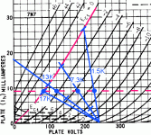
[2] Look up the tube's curves (http://www.nj7p.org/Tubes/PDFs/Frank/084-Several/7N7.pdf)
[3] draw a line horizontally on the 9 ma plate current graph
[4] "decide" on a plate voltage. I like 150 volts.
[5] draw the line vertically UP from 150 volts to the horizontal line.
[6] NOTE (estimate) where the grid voltage is going to be (half way tween –2 and –4 volts)
OK. –3 volts.
[7] Use E = IR … = 3 V = 9 ma • R = 3 ÷ 0.009 = R = 333 Ω.
This will be the cathode resistor.
[8] Choose a plate dynamic range. I like 50 volts.
[9] The PLATE resistor is (50 V; I = 0.009 A. R = E/i) = 50/.009 = 5.6 kΩ
Now the "basic section" is done.
It is your choice as to whether to use a cathode bypass capacitor (for added gain).
If you do then:
[10] Choose a low frequency cutoff. I like 5 Hz.
[11] Using "Z = 1/(2π FC)" set Z equal to the cathode resistor (5600 Ω), F = 5 Hz
5600 = ½ π 5 C
C = 0.00000568
C = 5.6 μF
Now that part is done.
Lastly, figure out (if you're going to use one) the output DC blocking capacitor. Generally, figure output impedance to be ½ the Rplate… as a good 'rule of thumb' value.
½ (5600) = 2800; Remember we "like" 5 Hz.
Z = 1/(2 π FC) … C = 1/(2 π FZ) = 11.4 μF.
CHOOSE NEXT HIGHER STANDARD VALUE. This gets "even lower" than 5 Hz. Or, next lower value, for economy. A 12 μF 350 V capacitor can be expensive. In this case though, a 10 μF isn't going to be too bad. And perfectly "sonic".
As to the type of a capacitor?
Dealer's choice.
I'm happy with electrolytics. Most people don't like 'em. But this is definitely a polarized capacitor's sweet spot.
However, there is this very nice film capacitor that will perform excellently:
http://www.mouser.com/ProductDetail...=sGAEpiMZZMv1cc3ydrPrFxjzI7V0kgrk68MiUidSptQ=
And there you go.
Easy-peasy.
Works every time.
GoatGuy
[1] Choose a plate current (you did: 9 ma)
[2] Look up the tube's curves (http://www.nj7p.org/Tubes/PDFs/Frank/084-Several/7N7.pdf)
[3] draw a line horizontally on the 9 ma plate current graph
[4] "decide" on a plate voltage. I like 150 volts.
[5] draw the line vertically UP from 150 volts to the horizontal line.
[6] NOTE (estimate) where the grid voltage is going to be (half way tween –2 and –4 volts)
OK. –3 volts.
[7] Use E = IR … = 3 V = 9 ma • R = 3 ÷ 0.009 = R = 333 Ω.
This will be the cathode resistor.
[8] Choose a plate dynamic range. I like 50 volts.
[9] The PLATE resistor is (50 V; I = 0.009 A. R = E/i) = 50/.009 = 5.6 kΩ
Now the "basic section" is done.
It is your choice as to whether to use a cathode bypass capacitor (for added gain).
If you do then:
[10] Choose a low frequency cutoff. I like 5 Hz.
[11] Using "Z = 1/(2π FC)" set Z equal to the cathode resistor (5600 Ω), F = 5 Hz
5600 = ½ π 5 C
C = 0.00000568
C = 5.6 μF
Now that part is done.
Lastly, figure out (if you're going to use one) the output DC blocking capacitor. Generally, figure output impedance to be ½ the Rplate… as a good 'rule of thumb' value.
½ (5600) = 2800; Remember we "like" 5 Hz.
Z = 1/(2 π FC) … C = 1/(2 π FZ) = 11.4 μF.
CHOOSE NEXT HIGHER STANDARD VALUE. This gets "even lower" than 5 Hz. Or, next lower value, for economy. A 12 μF 350 V capacitor can be expensive. In this case though, a 10 μF isn't going to be too bad. And perfectly "sonic".
As to the type of a capacitor?
Dealer's choice.
I'm happy with electrolytics. Most people don't like 'em. But this is definitely a polarized capacitor's sweet spot.
However, there is this very nice film capacitor that will perform excellently:
http://www.mouser.com/ProductDetail...=sGAEpiMZZMv1cc3ydrPrFxjzI7V0kgrk68MiUidSptQ=
And there you go.
Easy-peasy.
Works every time.
GoatGuy
Last edited:
There are other solutions.
Artosalo has a good one via a modern Circuit Modeling software packege.
They work too.
But "my method" as old-fashioned as it is, can be done with a slide-rule.
Which I no longer use, alas.
But millions of circuits (now legendary) were done WITHOUT computers.
And simulation.
And they worked.
GoatGuy
Here is a very good and simple explanation about graphical analysis and how to create a load line. Starting at page 36.
http://www.tubebooks.org/Books/York_Amplifiers.pdf
http://www.tubebooks.org/Books/York_Amplifiers.pdf
How much supply voltage do you have available ?
Here is one example:
It's suitable I have 240VAC tx
")
"How to design a triode section" (by me)
[1] Choose a plate current (you did: 9 ma)
[2] Look up the tube's curves (http://www.nj7p.org/Tubes/PDFs/Frank/084-Several/7N7.pdf)
[3] draw a line horizontally on the 9 ma plate current graph
[4] "decide" on a plate voltage. I like 150 volts.
[5] draw the line vertically UP from 150 volts to the horizontal line.
[6] NOTE (estimate) where the grid voltage is going to be (half way tween –2 and –4 volts)
OK. –3 volts.
[7] Use E = IR … = 3 V = 9 ma • R = 3 ÷ 0.009 = R = 333 Ω.
This will be the cathode resistor.
[8] Choose a plate dynamic range. I like 50 volts.
[9] The PLATE resistor is (50 V; I = 0.009 A. R = E/i) = 50/.009 = 5.6 kΩ
Now the "basic section" is done.
It is your choice as to whether to use a cathode bypass capacitor (for added gain).
If you do then:
[10] Choose a low frequency cutoff. I like 5 Hz.
[11] Using "Z = 1/(2π FC)" set Z equal to the cathode resistor (5600 Ω), F = 5 Hz
5600 = ½ π 5 C
C = 0.00000568
C = 5.6 μF
Now that part is done.
Lastly, figure out (if you're going to use one) the output DC blocking capacitor. Generally, figure output impedance to be ½ the Rplate… as a good 'rule of thumb' value.
½ (5600) = 2800; Remember we "like" 5 Hz.
Z = 1/(2 π FC) … C = 1/(2 π FZ) = 11.4 μF.
CHOOSE NEXT HIGHER STANDARD VALUE. This gets "even lower" than 5 Hz. Or, next lower value, for economy. A 12 μF 350 V capacitor can be expensive. In this case though, a 10 μF isn't going to be too bad. And perfectly "sonic".
As to the type of a capacitor?
Dealer's choice.
I'm happy with electrolytics. Most people don't like 'em. But this is definitely a polarized capacitor's sweet spot.
However, there is this very nice film capacitor that will perform excellently:
http://www.mouser.com/ProductDetail...=sGAEpiMZZMv1cc3ydrPrFxjzI7V0kgrk68MiUidSptQ=
And there you go.
Easy-peasy.
Works every time.
GoatGuy
Thanks for the tutorial/guide I guees only valid for triode operation?
Best
Felipe
Funny, I'm a guitar amp guy hardly ever post here, but read through now and then, was just looking at this today and then saw this post. Dusty old preamp w/ 7F7s but amp is using 7N7s. Maybe you can find some use.
http://www.updatemydynaco.com/HistoricDocuments/WilliamsonAmplifierKeroes.pdf
http://www.updatemydynaco.com/HistoricDocuments/WilliamsonAmplifierKeroes.pdf
> the cathode resistor (5600 Ω)
I *think* you meant to grab 333 Ohms (from step 7). You seem to have grabbed the plate load.
> cathode bypass capacitor ...low frequency cutoff. I like 5 Hz.
> Using "Z = 1/(2π FC)" set Z equal to the cathode resistor (5600 Ω), F = 5 Hz
> 5600 = ½ π 5 C
Strictly, you want to bypass Re||(1/Gm), the tube's internal cathode impedance.
merlin has picked a current right off the datasheet. Gm also depends on plate voltage, so we have a choice of 3,000uMho or 2,600uMho. 333 Ohms or 385 Ohms.
Take the lower value (bigger cap).
So far we have 333||333 or like (sliderule) 160 Ohms. At 5Hz this is 193uFd.
Caps vary 20%. Tubes vary 20%. If we MUST hit -3dB @ 5Hz, we better allow another 40%. 270uFd.
Strictly we should factor-in the plate load 5,600 divided by Mu. 5600/20 is 280 more Ohms which appears in series with internal cathode impedance 1/Gm.
333||(333+280)= 215 Ohms. Compare to 160 Ohms neglecting Rl/Mu.
Rules-O-Thumb:
1/Gm will be very similar to Rk in most practical designs. (Small triode at 9mA is pushing the limits and should be checked.) So it is expedient to compute on HALF of Rk to pick Ck.
Rl/Mu is generally a small correction, and is "conservative" (results will be better than computed) so this is often neglected.
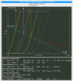
I actually plotted the picture. Agree that ~~5K Rl makes more sense than my extreme bad-examples. 1.5K has low gain. 17K has no swing. ~~7K is a split-difference. I have used larger swings than 50V up, but that works fine also.
I *think* you meant to grab 333 Ohms (from step 7). You seem to have grabbed the plate load.
> cathode bypass capacitor ...low frequency cutoff. I like 5 Hz.
> Using "Z = 1/(2π FC)" set Z equal to the cathode resistor (5600 Ω), F = 5 Hz
> 5600 = ½ π 5 C
Strictly, you want to bypass Re||(1/Gm), the tube's internal cathode impedance.
merlin has picked a current right off the datasheet. Gm also depends on plate voltage, so we have a choice of 3,000uMho or 2,600uMho. 333 Ohms or 385 Ohms.
Take the lower value (bigger cap).
So far we have 333||333 or like (sliderule) 160 Ohms. At 5Hz this is 193uFd.
Caps vary 20%. Tubes vary 20%. If we MUST hit -3dB @ 5Hz, we better allow another 40%. 270uFd.
Strictly we should factor-in the plate load 5,600 divided by Mu. 5600/20 is 280 more Ohms which appears in series with internal cathode impedance 1/Gm.
333||(333+280)= 215 Ohms. Compare to 160 Ohms neglecting Rl/Mu.
Rules-O-Thumb:
1/Gm will be very similar to Rk in most practical designs. (Small triode at 9mA is pushing the limits and should be checked.) So it is expedient to compute on HALF of Rk to pick Ck.
Rl/Mu is generally a small correction, and is "conservative" (results will be better than computed) so this is often neglected.
I actually plotted the picture. Agree that ~~5K Rl makes more sense than my extreme bad-examples. 1.5K has low gain. 17K has no swing. ~~7K is a split-difference. I have used larger swings than 50V up, but that works fine also.
Attachments
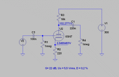
As was previously stated, the Loctal 7N7 is electrically equivalent to the Octal 6SN7. With its μ of 20, using that triode wired common cathode may yield too much gain. The hybrid setup I've uploaded has a stage gain of about 8X. Even that may be too much. The non-inverting LTP based setup provided can be easily altered to add loop NFB, which allows gain to be customized.
Attachments
Last edited:
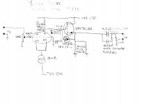
How much supply voltage do you have available ?
Here is one example:
Are necessary C3 (all my sources have output cap) & R1 (I use 100K ladder attenuator)?
I'ts necessary elevate the heater?
TIA
Attachments

@GoatGuy
I believed the output coupling cap is related for the input impedance of the next stage?
Yes, if you want it to be minimal.
Otherwise, the minimal value just defines the lower bound.
Anything (reasonable) larger works too. And extends the bass response subtly, up to about 10× the minimum value.
GoatGuy
- Status
- This old topic is closed. If you want to reopen this topic, contact a moderator using the "Report Post" button.
- Home
- Amplifiers
- Tubes / Valves
- Looking for 7N7 preamp schematic