Maybe I'm missing the point, but couldn't you just strap them?
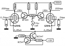
I'am guessing you mean tie the screens together. Unlike the triode LTP current flows in the screens which does not get to the plates. If the screen currents are not the same (valve mismatch) then the plate currents become different too so the LTP looses its AC balance. If you can make the screen currents equal then the plate currents become equal again. The NPN solution returns the screen current back to the plate while maintaining a constant screen voltage - so what starts in the cathode ends up in the plate resistors. I think that's some sort of explanation.
Two more examples of amplifiers with LTP inverter with pentodes.
The Philips EL3720 uses 2 x EF80 (= 6BX6).
The (hefty) Philips EL6471 uses 2 x E80L (= 6227).
You're right with two E80L's in the Philips EL6471. But they aren't used as the phase splitter, as this amplifier is fully symmetric. They're the 2nd voltage amplfier stage. Phase inversion, if needed at all, is done in the input transformer.
Best regards!
Good linearity with pentodes, forget it.I needed the gain as I took the NFB back to this stage rather than the first stage. I also wanted good linearity, high drive and not having miller capacitance.
No Miller, at least much less compared to triodes.
High drive, is relative.
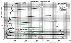
Tryed a 6AH6 (on "paper"), looks like this.
Mona
Attachments
Last edited:
Interesting comments you pose. First this an amp I have built and measured THD on. Here are plots of open loop the distortion at the first stage, the LTP outputs and the speaker at 50W (clipping = 120W).


If you believe simulation and the Alumi valve models you can see the first stage is very clean and the output stage is the biggest contributor to distortion. I would say the NPN idea of returning the screen current back to the plate would have helped a lot in matching.
If you believe simulation and the Alumi valve models you can see the first stage is very clean and the output stage is the biggest contributor to distortion. I would say the NPN idea of returning the screen current back to the plate would have helped a lot in matching.
- Status
- This old topic is closed. If you want to reopen this topic, contact a moderator using the "Report Post" button.
- Home
- Amplifiers
- Tubes / Valves
- Long Tail Pair Phase Inverter with Pentode?