I think Steve claims Cinemag can be cheaper at same quality
somewhere int here: diyAudio - Search Results
coax vs shielded twisted pair, shield termination options really depend on "threat environment"
somewhere int here: diyAudio - Search Results
coax vs shielded twisted pair, shield termination options really depend on "threat environment"
Loren42,
I've done some thinking about your long cable issue. Blue Jeans, IIRC, uses a simple coaxial construction, which is not suited to the task at hand. Shielded "twinax" in a differential, if not true balanced, configuration seems correct. That length of shield, when carrying signal, can all too easily pick up noise.The shield should not carry signal and only be connected to the upstream end chassis, not signal, ground.
You previously mentioned wall plates. 2X Neutrik 203Ms will do the job for you. Online Components carries the Neutrik plates.
No ifs, buts, or maybes, you will have to buffer the PAS preamp. I'm giving the buffer some thought. More about that to to follow soon. However, this much is clear. You will need trafos to break ground loops up. Jensen can be pricey. CineMag offers competetive products, at lower cost. CineMag's CMOB-2L looks like a candidate for your situation. A DC blocking cap. is needed between the buffering voltage follower and the trafo. Contact CineMag for assistance in sizing that part.
Called CineMag and left a message.
Cinemag are great but can take a long time to get if they are not in stock.
I'm in the "Use high quality shielded cable (Belden, Mogami, Canare) and break the loop" camp.
That's what I do and it works well for me over about the same distance.
Fortunately, they had what I needed in stock and they should ship today! I am a happy camper. These will mount nicely inside my amp.
Long term I would like to roll my own preamp, but in the interim, does it make sense to upgrade the PAS 3 with one of those Tubes4HiFi PC boards?
I would not spend much on the PAS, if you are going to build soon. The buffer you build for the PAS will serve you well in combination with the new, DIY, preamp.
The awkward cabling situation will not disappear and you will already have the circuitry needed to cope with it. Given the presence of a competent buffer, a nice sounding 12B4 based line stage could work out very well.BTW, asking the 'X7 triode to drive both the power amp and tone control circuitry, as was done in the old Dyna PAS preamps, is problematic. AVA offers PAS rebuild kits that eliminate the troublesome tone controls. I can tell you from 1st hand experience that the AVA stuff is good. My son uses a rebuilt PAS of mine hand me down.
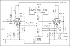
I've uploaded a schematic for a single channel that shows just how complicated good tone controls are. Also, it is a fact that few recordings benefit from tone controls. Therefore, tone controls, if present, should be capable of being totally switched out of the signal path.Attachments
Last edited:
Eli,
Yes, I want to add a defeat switch for the tone controls.
The circuit presented is a little hard to read (too small when expanded), but it looks like the output impedance is going to impact the tone circuit. Is that true?
The next step would be drilling down to a good recommended circuit that I could not only use for my next amp, but could also transplant into my PAS.
Having an active tone network would be the cat's meow versus the circuit used now in the PAS.
Other than the commercially available upgrades, leave the PAS alone, if no reason other than severe PSU limitations.
PM me with your EMail address and I'll send you the high resolution, .bmp, version of that Max Robinson designed tone control setup. 4X 12AX7s for 2 channels of tone controls is (IMO) OTT. It doesn't take much effort to replace the cap. coupled cathode followers with DC coupled ZVN0545A source followers and reduce the bottle count to 1/channel.
As Max's design is "unity" gain, my inclination is to switch the tone control circuitry in/out of the signal path right at the line stage's I/Ps.
FWIW, the PSU I have in mind for the cable driver buffer will easily support a 12B4 line stage, along with the buffer. Perhaps a combined line stage/buffer effort is in order, as you will avoid some duplicated work. Ignore the PSU in the uploaded 12B4 line stage schematic. FWIW, the 12B4 line stage can drive a 10 KOhm I/P impedance amp, IF the interconnect cabling is reasonably low capacitance. Your situation is anything but reasonable.
PM me with your EMail address and I'll send you the high resolution, .bmp, version of that Max Robinson designed tone control setup. 4X 12AX7s for 2 channels of tone controls is (IMO) OTT. It doesn't take much effort to replace the cap. coupled cathode followers with DC coupled ZVN0545A source followers and reduce the bottle count to 1/channel.
As Max's design is "unity" gain, my inclination is to switch the tone control circuitry in/out of the signal path right at the line stage's I/Ps.
FWIW, the PSU I have in mind for the cable driver buffer will easily support a 12B4 line stage, along with the buffer.
Perhaps a combined line stage/buffer effort is in order, as you will avoid some duplicated work. Ignore the PSU in the uploaded 12B4 line stage schematic. FWIW, the 12B4 line stage can drive a 10 KOhm I/P impedance amp, IF the interconnect cabling is reasonably low capacitance. Your situation is anything but reasonable. Attachments
Hurray!Fortunately, they had what I needed in stock and they should ship today! I am a happy camper.
 I'm sure you'll like them.
I've uploaded the 1st cut schematic for buffering the PAS. Assistance from CineMag is needed in properly sizing the DC blocking cap., that's in the O/P circuitry.
If a combined 12B4 line stage/buffer project is to be undertaken, the FET will be DC coupled to the triode. Fewer caps. in the signal path is "always" better.
If a combined 12B4 line stage/buffer project is to be undertaken, the FET will be DC coupled to the triode. Fewer caps. in the signal path is "always" better.
Attachments
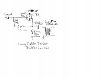
I've uploaded the 1st cut schematic for buffering the PAS. Assistance from CineMag is needed in properly sizing the DC blocking cap., that's in the O/P circuitry.
If a combined 12B4 line stage/buffer project is to be undertaken, the FET will be DC coupled to the triode. Fewer caps. in the signal path is "always" better.
Thanks, Eli.
I ended up ordering two CineMag CMLI-15/15B transformers as per Dave's recommendation at CineMag.
This transformer is supposed to be located in the power amp.
CMLI-15/15B[PC] <Single Shield> - CMLI-15/15B2[PC] <Dual Shields>
Parameter
Conditions
Typ
Turns Ratio1 : 1.00
Input impedance, Zi
1 kHz, +4 dBu RL=15k Test Circuit 1
1 kHz, +4 dBu RL=10k Test Circuit 1
18.0 kS
13.0 kS
Voltage Gain
1 kHz, +4 dBu Test Circuit 1 Rs=600S RL=15 kS
-2.2 dB
Distortion (THD+N%)
1 kHz, +4 dBu Test Circuit 1 Rs=600 RL=15K
20 Hz, +4 dBu Test Circuit 1 Rs=600 RL=15K
0.0007%
0.02%
Max 20 Hz input level
1.0% THD; Rs=600S Rl=15KS Test Circuit 1
+20 dBu
Response, ref 1 kHz
20 Hz +4 dBu Rs=600S RL=15KS Test Circuit 1
20 kHz +4 dBu Rs=600S RL=15KS Test Circuit 1
-0.03 dB
-0.1 dB
Phase Shift at 20Hz
Phase Shift at 20 kHz
Referenced to source generator Test Circuit 1
+1E
-18E
CMRR Single Shield
CMRR Dual Shield
60 Hz Test Circuit 2 per IEEE Std 389-1996 ¶19 RL=15KS
1 kHz Test Circuit 2 per IEEE Std 389-1996 ¶19 RL=15KS
60 Hz Test Circuit 2 per IEEE Std 389-1996 ¶19 RL=15KS
1 kHz Test Circuit 2 per IEEE Std 389-1996 ¶19 RL=15KS
103 dB
76 dB
110 dB
87 dB
Operating Temp Range
Operation and storage
0E C Min 70E C Max
OK, then cross out the trafo in the buffer cuicuit I uploaded. The buffer's O/P cap. will be a 4.7 μF. metalized polypropylene (MPP) part, like a Solen. Bypass the MPP part with a film and foil part up to 0.47 μF. in value. The low cost bypass is a 716P "Orange Drop". The boutique bypass cap. is a MultiCap PPFX series part.
I strongly suspect you will be mounting the trafos you bought from CineMag in a separate enclosure that's positioned closely to the power amp.
If you already own LONG Blue Jeans cables, send them back to be remanufactured into a number of cable sets whose length is suited to use near the system control center. As I explained earlier in this thread, this situation requires that cable shielding NOT carry signal. As you are constructing a highly custom installation, make the interconnect cabling "captive", wherever possible. Fewer purely mechanical connections in the signal path is good. For instance, hard wire the cabling between the buffer and the wall plates to the buffer. Obviously, XLR connectors are necessary, at the wall. Strain relief of "captive" wiring is easy. The cable passes through holes in the sheet metal that contain rubber grommets. Inside the box, you tie a figure 8 knot, that holds a piece of wooden doweling, with the wire.
Last edited:
I strongly suspect you will be mounting the trafos you bought from CineMag in a separate enclosure that's positioned closely to the power amp.
Well, I plan to mount the two transformers inside the power amp close to the input PC board. I'll make a set of custom clamping brackets out of some 1/4" plate aluminum.
I have not bought cables. However, what do you recommend for the twinax line cable?
Normally, when I do a strain relief I use either a rubber grommet or I turn one from nylon on my lathe (it is good to have a private machine shop in your garage
) and use a nylon tie wrap on the inside to prevent the cable from pulling back out.I'll post a wiring diagram and schematic once we get all the details ironed out so that you have a chance to do a final review of my intentions.
I appreciate the help you are providing as well as the education.
I see I am too late to be useful, but I have a Jensen CI-2RR on an input to my preamp for galvanic isolation and I cannot say enough good things about it.
A project I am currently working on is using Jensen JT-6110K-B's at the input to my power amp.
My advice for the cable for the long run between the preamp and transformer would be to use unshielded twisted pair rather than coax. I do not see the need to modify your preamp at all.
A project I am currently working on is using Jensen JT-6110K-B's at the input to my power amp.
My advice for the cable for the long run between the preamp and transformer would be to use unshielded twisted pair rather than coax. I do not see the need to modify your preamp at all.
Last edited:
I see I am too late to be useful, but I have a Jensen CI-2RR on an input to my preamp for galvanic isolation and I cannot say enough good things about it.
A project I am currently working on is using Jensen JT-6110K-B's at the input to my power amp.
My advise for the cable for the long run between the preamp and transformer would be to use unshielded twisted pair rather than coax. I do not see the need to modify your preamp at all.
The PAS 3 preamp has no buffer stage. The output comes straight from the passive tone controls and Dynaco expects a terminating impedance of 100 KΩ or higher.
If the impedance is much lower it changes the tone circuit operation drastically.
The PAS 3 preamp has no buffer stage. The output comes straight from the passive tone controls and Dynaco expects a terminating impedance of 100 KΩ or higher.
If the impedance is much lower it changes the tone circuit operation drastically.
But you said your amp had an input impedence of 10K?
Had I seen the thread before you bought the transformers I might have suggested the JT-6110K-B step-down transformer to give you a higher input impedence, assuming you have enough voltage to use the JT-6110K-B and still drive your amp.
Still I would try the system with the transformers first before modifying the preamp. And I would not use shielded cable. Shielded cable grounded at the source can act as an antenna. I was getting pretty good shortwave reception that way here.
Forgive any ignorance on my part, my Dynaco is a PAT-4 and I realize I may have ventured into the wrong forum.
Guys pay attention, please! The sort of transformers under discussion need to be driven by low impedance sources. Look at the trafo data sheets, closely. Dyna PAS preamps are anything but low impedance sources. The approx. 470 KOhm I/P impedance of Dyna tubed power amps is not accidental. Sometimes, tweaking of the secondary side loading to stop ringing is necessary.
BTW, even if the PAS did not impedance mismatch with the ground loop blocking trafo, the capacitance of 20 ft. shielded cables will roll the HF info. off., very badly.
Build the buffer!
The approx. 470 KOhm I/P impedance of Dyna tubed power amps is not accidental. Sometimes, tweaking of the secondary side loading to stop ringing is necessary.BTW, even if the PAS did not impedance mismatch with the ground loop blocking trafo, the capacitance of 20 ft. shielded cables will roll the HF info. off., very badly.
Build the buffer!
- Status
- This old topic is closed. If you want to reopen this topic, contact a moderator using the "Report Post" button.
- Home
- Amplifiers
- Tubes / Valves
- Long Preamp to Power Amp Cable Lengths