Another issue is the horn shape. I would have loved circular horns, but it becomes very much impossible if I want them to radiate quasi-cylindrical wavefronts ...
Why do you want quasi-cylindrical wavefronts? Is this some kind of line array? Not for home use I presume.
Member
Joined 2003
Why do you want quasi-cylindrical wavefronts? Is this some kind of line array? Not for home use I presume.
well, no not exactly home use. But not classic "PA" either. Something a bit strange and experimental, really.
I am not after a line array per se, but rather line sources, at least for the frequencies above ~500 or so.
If I want to avoid lobing while using multiple identical drivers in one band, I have to avoid spacing the sound emitters apart more than 1/3rd wavelengths center-to-center distance, or better even no more than 1/4th wavelengths. As I understand it, the pictured waveguide manufactured by turbosound effectively does line up acoustically small orifices all radiating pretty much in-phase at their termination, and then leading into further horizontal horn expansion of some sort. one could call that an approximation of a line emitter radiating some approximation of cylindrical wavefronts, which is one way to achieve the goal of using multiple (HF) drivers for one band, all in order to increase maximum, least distorted output without lobing.
Last edited:
Meko,Thanks Art! The graphs are quite interesting.
1)How do you think these deviations actually occur? Are they simply cancellations/peaks caused by the dimensions and shape of the paraline path?
2)If I consider wavefront-shaping, I think I would go the rather "low-tech" route of the classic micro-capillary pathlength-difference systems like this rather nicely engineered example by turbosound, since total horn depth is not that much of an issue and the creation of the parts would be manageable using cnc routing machines, which I fortunately have access to.
3)Of course another problem is the crossover area from, say, a line-source array of massive phenolic 2" drivers to a line-source array of 1" drivers in the area of 5...7k. Maybe I could get away with filters a little steeper, but maybe not.
1) Sound waves like to go straight. Bad things happen to them when they have to go around obstacles in their path
") .
.2) The Paraline and the Turbosound and all the other line array path length equalizing devices do the same thing. I don't consider either to be "low tech", though the 90 and 180 degree turns in the Paraline may roughen frequency response a bit more than the smoother bends employed in other devices. Response using any of the devices won't be as smooth as typical horns without.
3) Regardless of filters, splitting the HF range in two will result in lobing in either the vertical or horizontal response, depending on whether the horns are above or side by side. Considering there are dozens of driver choices that can cover the range of 800 to 18,000 Hz using diaphragms made of metal or plastic or combinations of the two, I see no reason to mess up the polar response with two sets of drivers and horns covering that range.
Art
Using multiple HF drivers in a line array makes the construction of path length equalization devices simpler, as there is not as much path length differences with three compared to one device covering the same vertical dimension. There are line arrays with as many as 10 or more HF drivers in one box, requiring hardly any path length equalization.I've recently noticed a trend for 3 inline/line array tweeters, one design using a kind of waveguide- which seem to work well; is this because of the central tweeter somehow lessening the effect of lobing and adding a more spacial sound?
Right, it is intuitive and it is exactly that reason that I dislike the whole idea for - I just recall Tom Danley explain that the internal dimensions are so small acoustically that it will act more like a simple pressure that does not necessarily act like one would intuitively expect "soundwaves" to act. Well it seems there is no free lunch, as always. A matter of tradeoffs and decisions, so thanks for helping me along the way.1) Sound waves like to go straight. Bad things happen to them when they have to go around obstacles in their path
Art
2) The Paraline and the Turbosound and all the other line array path length equalizing devices do the same thing. I don't consider either to be "low tech", though the 90 and 180 degree turns in the Paraline may roughen frequency response a bit more than the smoother bends employed in other devices. Response using any of the devices won't be as smooth as typical horns without.
Art
Yeah, I called it "low tech" because I consider Tom Danley's approach very "smart" in terms of manufacturing expenses, size and because of the straight, elegant simplicity of concept.
I have a better intuitive feel about the other style though, when it is as nicely executed as turbosound for example.
3) Regardless of filters, splitting the HF range in two will result in lobing in either the vertical or horizontal response, depending on whether the horns are above or side by side. Considering there are dozens of driver choices that can cover the range of 800 to 18,000 Hz using diaphragms made of metal or plastic or combinations of the two, I see no reason to mess up the polar response with two sets of drivers and horns covering that range.
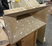
Well, I have recently built a large prototype expo-conical Horn roughly based on Keele's CE horn concept (image). It was designed to control horizontal directivity down to around 400Hz, and the constant directivity qualities are pretty satisfying.
A DH1A is attached to the horn and plays adequately from 500 up to 18k or so, using a little EQ on the high end it is acceptably linear.
However, I am currently trying to get away from these concepts pushing so many octaves through a horn because I felt like I was in need of more transparency, precision and resolution. However, like I already mentioned, I am currently still trying to map out the way to achieve that.
Attachments
Removing the 500-1000 Hz octave from the HF driver will go a long way towards transparency, precision and resolution, and can be accomplished with the DH1A using 6" or 8" speakers mounted on the same horn, as in the DSL SH(Synergy Horn) 95, resulting in a virtual single driver point source covering from as low as 100Hz (using bass reflex porting of the horn enclosure) to 18kHz. No lobes.A DH1A is attached to the horn and plays adequately from 500 up to 18k or so, using a little EQ on the high end it is acceptably linear.
However, I am currently trying to get away from these concepts pushing so many octaves through a horn because I felt like I was in need of more transparency, precision and resolution. However, like I already mentioned, I am currently still trying to map out the way to achieve that.
Removing the snout adapter on the DH1A reduces the throat to 1.4", which also makes it easier to build a horn with better HF properties, and better facilitates the offset horn mid drivers.
Art
Last edited:
Removing the 500-1000 Hz octave from the HF driver will go a long way towards transparency, precision and resolution, and can be accomplished with the DH1A using 6" or 8" speakers mounted on the same horn, as in the DSL SH(Synergy Horn) 95.
I agree, removing that octave would help a lot. However many advantages the synergy concept may have, highest efficiency is still one of the main goals with my project and I like classic horn design a lot.
Yeah, for this prototype, an aluminium tube is reaching into the snout of the DH1A that forms the first 5cm of the horn and also the transition from circular to a square profile and prevents the exit to widen to the 2" dia. I actually did try removing the snout once (with heating the bolts, probably not enough), but my tools broke in the process- so much for locktite.Removing the snout adapter on the DH1A reduces the throat to 1.4", which also makes it easier to build a horn with better HF properties, and better facilitates the offset horn mid drivers.
However many advantages the synergy concept may have, highest efficiency is still one of the main goals..
But if you are going for constant directivity, efficiency (well, actually, sensitivity I guess) will be no more than that of the tweeter after CD equalization has been applied. The sky high numbers for many tweeter compression drivers usually only happens in their midbands. Those would all be EQd down to the sensitivity of the driver at ~15kHz or higher. The horn systems with 103dB+ sensitivity will usually use exponential horns and be beaming at the high frequencies unless a supertweeter is also used.
Hi Bill.
What you say is true of any CD device that is feed by a direct radiating tweeter, but for a compression device there is still some gain to be had (over that of a direct radiating driver of the same area) from the compression ratio. But yes, the overall efficiency of the HF device in a CD waveguide is that at the upper end of its bandwidth. This is a big boon to any excursion limitations however.
What you say is true of any CD device that is feed by a direct radiating tweeter, but for a compression device there is still some gain to be had (over that of a direct radiating driver of the same area) from the compression ratio. But yes, the overall efficiency of the HF device in a CD waveguide is that at the upper end of its bandwidth. This is a big boon to any excursion limitations however.
The sky high numbers for many tweeter compression drivers usually only happens in their midbands.
Thanks for the reply. I know, and that is part of my (not really solveable) problem. Like I mentioned, I am after non-metallic / probably phenolic 2" mids. The JBL2482 for example gets really a lot quieter from around 5k up. I would then use it from 600 to 5k. Three octaves. The throat is too wide for anything much above that anyways. And they are not tweeters. Alnico flux loss being another thing. With a proper (actually loading) expo-ish / partly conical horn, it will end up with an average (on-axis) sensitivity of over 110 dB@1w@1m if radiating into somthing like a ~60°x60° sphere segment or equivalent. Then a crossover to a (super)tweeter-array is planned. With all the problems involved... lots to think through.
The horn systems with 103dB+ sensitivity will usually use exponential horns and be beaming at the high frequencies unless a supertweeter is also used.
Yeah, the system is going to be 5-way and it doesn't have the strongest focus on constant directivity. Everything below ~600Hz is clear to me but the lobing / efficiency conflict is really a thing.
Last edited:
Earl,
Yes, I wasn't knocking the constant directivity systems, just warning not to be deceived by ultra-sensitive specs of horn setups that might be only doing it by beaming the highs on-axis. When radiation is evened out over an area (rather than just a point), more realistic numbers will result.
Yes, I wasn't knocking the constant directivity systems, just warning not to be deceived by ultra-sensitive specs of horn setups that might be only doing it by beaming the highs on-axis. When radiation is evened out over an area (rather than just a point), more realistic numbers will result.
Bill, I understood, but I thought that there might be some room for misunderstanding. I have often made the point that the efficiency gains in a horn system come mostly from the compression ratio, not the horn, which is, I think part of your point as well. A DE250 in a CD waveguide has just enough output to match a high efficiency woofer (like a 15TBX100) at the crossover if it is design to be flat on axis. The woofer is rated at say 96 dB and the DE250 at 103 dB. This, I think is your point.
This is also why I say that if the un-EQ'd waveguide system is not falling at about 6 dB/oct, then it cannot be constant directivity.
Also part of your point is the fact that the perceived "high end" is not simply the axial response. Flat on-axis does not sound the same when the system in CD when compared to a beaming device. This results in a wide variety of perceptions based on expectation. A CD device that is flat on axis will sound very bright.
Earl,A DE250 in a CD waveguide has just enough output to match a high efficiency woofer (like a 15TBX100) at the crossover if it is design to be flat on axis. The woofer is rated at say 96 dB and the DE250 at 103 dB. This, I think is your point.
This is also why I say that if the un-EQ'd waveguide system is not falling at about 6 dB/oct, then it cannot be constant directivity.
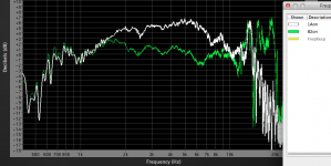
The fall off is also determined by diaphragm construction, as you can see below the B&C DE82 using a 3" voice coil mylar/titanium diaphragm actually shows a rising upper response compared to a 3" all titanium diaphragm EV DH1A, which more or less falls at about 6 dB per octave. Both were measured on the very narrow constant directivity Maltese horn, midband sensitivity for the DH1 is around 115 dB one watt one meter (2 volts, nominal 16 ohm diaphragm). The mylar surround throws away midband sensitivity, but increases the upper sensitivity.
Using the Maltese HF horns requires some serious low mid and bass horns to match sensitivity. Also requires a rather small listening window, unless the distance is long, 11 degrees only covers about 3 feet of my couch..
Art
Attachments
Last edited:
So you are saying the B&C DE82 diaphragm is breaking up.If the diaphragm is rigid then it has to fall at 6 dB / oct. Only a diaphragm that is breaking up can do otherwise.
Seems to be a fairly common design approach.
The B&C DE82 still sounded OK when EQed, though it couldn't get as loud as the DH1A before distortion became objectionable.
I wish I had received the "TN" all titanium diaphragm, the mylar/titanium had been put in by mistake.
Art
Its just simple physics that a single degree of freedom system has to fall at 6 dB/Oct below resonance. If there is more velocity than this then there has to be multiple motions (more degrees of freedom) in the moving system. Usually this is the surround. JBL did a paper on this some years back. I never liked the idea of using modes like this to "extend" the response, but it seems to be pretty common.
Its just simple physics that a single degree of freedom system has to fall at 6 dB/Oct below resonance. If there is more velocity than this then there has to be multiple motions (more degrees of freedom) in the moving system. Usually this is the surround. JBL did a paper on this some years back. I never liked the idea of using modes like this to "extend" the response, but it seems to be pretty common.
Erm, hmm. I thought the first posts were talking about the power response falling off in a lowpass fashion at -6 dB/octave, due to the moving mass corner (or so I was classically taught-I'd think the situation is more complex than that).
But the next post says "6 dB/Oct below resonance" which is not what I thought was being discussed. So I'm a bit confused.
The other point
But the next post says "6 dB/Oct below resonance" which is not what I thought was being discussed. So I'm a bit confused.
The other point
raises an interesting philosophical question: if hardly anything is mixed on such speakers, is it really good to use them for playback?Also part of your point is the fact that the perceived "high end" is not simply the axial response. Flat on-axis does not sound the same when the system in CD when compared to a beaming device. This results in a wide variety of perceptions based on expectation. A CD device that is flat on axis will sound very bright.
My Bad! I meant to say -6dB/Oct above resonance.
Your "other point" is a good one that Toole often talks about. Music that is mixed on bad speakers and then listened to on good ones creates a problem (just like the other way around). Anyways, a lot of control room monitors are close to CD.
Your "other point" is a good one that Toole often talks about. Music that is mixed on bad speakers and then listened to on good ones creates a problem (just like the other way around). Anyways, a lot of control room monitors are close to CD.
Music that is mixed on bad speakers and then listened to on good ones creates a problem.
While it is true that this is a point very worth talking about, I have reason to believe it is not so simple. As with any creative process, the most important part of the equation is the creator, in this special case the mixing engineer and also the producer and the mastering engineer. While it may be advisable to perform all of these tasks on speakers that leave nothing to be desired (do they exist?), I can't stress this point enough: A good engineer sees the invisible, knows if something is there even if he/she can not actually hear it in any particular situation because of any one problem present, may it be a bad room, bad speakers, or anything else. He/she will have a very elaborate and very complete picture of the sonic characteristics even if the speakers may project that image in an uncomplete or even distorted way. Experience is the reason for that and of course it takes a lot of time.
I just wanted to say that I would be cautious about directly connecting the speakers used for a mixdown to the maximum possible quality of that mix. And I would also be cautious about thinking that a good mix done on "bad" speakers was merely a happy accident.
- Status
- This old topic is closed. If you want to reopen this topic, contact a moderator using the "Report Post" button.
- Home
- Loudspeakers
- Multi-Way
- lobing of drive units