Peter Daniel said:Because I want to experiment with placing them directly at the chip. Will have to install some sockets.
I was actually thinking about that, after looking at the triple capacitor combination on the evaluation board for the 4780. Here is the list of caps that they are using for theirs:
.1uF monolytic cermamic
10uF electolytic
1000uF electrolytic
I attached their BOM to this post.
--
Brian
Attachments
I am curious if 1000u is all they recommend per rail? It seems like a pretty low value for such powerful chip.
My Panasonics seem to work fine though. While in LM3875 they seem a bit laidback, with this amp this is not a case. There is plenty of highs, with good detail and no traces of glare and harshness. It's almost like switching from Aleph to AlephX")
My Panasonics seem to work fine though. While in LM3875 they seem a bit laidback, with this amp this is not a case. There is plenty of highs, with good detail and no traces of glare and harshness. It's almost like switching from Aleph to AlephX
Peter Daniel said:Looking at BOM, the caps are rated at 35V so the power is not at max levels.
If you look in the LM4780 datasheet, there is a similar BOM, but with 50v capacitor values. The BOM is dated June 2003, and the datasheet is dated July 2003, so I am guessing the values should be 50v, since you can run the amplifier with +/- 42v rails according to the datasheet.
--
Brian
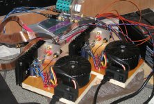
I will be coming up with a similar board design, as currently sold by Brian. Brian already volunteered to help with transfering the layout I don't see a reason why the board for LM4780 would have to be much bigger than the one currently available for LM3875. I used the same minimized schematic here (as I was using with LM3875) and everything works fine. The amps has actually less offset. It would be nice to combine again 2 amp's channels and 2 rectifying boards in one board. The setup will accomodate either 2 channel version or parallel amp version. There will not be any banana connections on a board, just plain hole to connect wires.
I will conduct more serious listening tests tomorrow, but initial findings indicate that this amp may be as good (or better) as what we are used to expect from a chip amp
I don't see a reason why the board for LM4780 would have to be much bigger than the one currently available for LM3875. I used the same minimized schematic here (as I was using with LM3875) and everything works fine. The amps has actually less offset. It would be nice to combine again 2 amp's channels and 2 rectifying boards in one board. The setup will accomodate either 2 channel version or parallel amp version. There will not be any banana connections on a board, just plain hole to connect wires.I will conduct more serious listening tests tomorrow, but initial findings indicate that this amp may be as good (or better) as what we are used to expect from a chip amp
Peter Daniel said:I will be coming up with a similar board design, as currently sold by Brian. Brian already volunteered to help with transfering the layout
I will conduct more serious listening tests tomorrow, but initial findings indicate that this amp may be as good (or better) as what we are used to expect from a chip amp
How about 2 amplifier boards, 2 power supply boards, and one bridging board for the DRV134? The bridging board wouldn't need to be that big. You are simply paralleling 2 channels, so it would easily drive a 2 ohm load, meaning that you could bridge two board (with 2 parallel channels each) and run a 4 ohm load just fine.
--
Brian
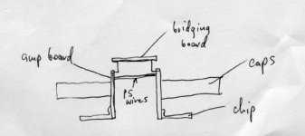
Sizewise, the amps board wouldn't be much bigger than the one used for LM3875. I still have to figure out how much capacitance is really required for best overall performance, but even with 1,500 the bass is very good. So it shouldn't be more than 3" x 1.5" big. It would include 2 jumpers, for either running channels in parallel or stereo. For bridging, I would suggest aligning them, with wires running through PS holes on each board, so power distribution is very much simplified. The amps board should have mirror image of PS acces points, which is not a problem (basically left and right version). The bridging board could be mounted on top, for even simpler layout. This would be one cool, high power amp module
What is really required for the bridging board, any schematic example?
What is really required for the bridging board, any schematic example?
Attachments
Peter Daniel said:What is really required for the bridging board, any schematic example?
It might be better to do it without a bridging chip, and just use a differential output amplifier. This would allow you to try different opamps, and even discrete opamps, such as used in the mox.
I got the below picture from my school lecture notes. You can find it here:
http://users.ece.gatech.edu/~mleach/ece3050/Sp04Notes/OpAmps01.pdf
on page 18, with a description of how to calculate the values.
For the application of bridging, you would make Rf1 = R1 and Rf2 = 2*Rf1. A good value to try might be 1k for R1.
--
Brian
Attachments
What about using a simple differential pair at the input to split signal into inverted and noninverted sides? Something similar to what is used in Aleph X or here: http://www.metaxas.com/pages/technology/diy.html (check OUTPUT STAGE DESIGN section)
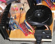
The transformenr I'm using here is double 22V AC secondaries, 300VA Plitron. This produces around +/-34V DC on rails.
I never used no centertap transformer with virtual ground, so I can't comment on that.
I tried adding 5,600u Nichcons directly after rectifiers and the sound degraded substantially. I will stick with 1000 per rail only. Also adding 4.7BG N on rectifiers board, improves performance, so they would be recommended.
cdoggy81 said:
Looks like an invitation to present a new design. I might come up with it today. It is very simple and not much to think about
- Status
- This old topic is closed. If you want to reopen this topic, contact a moderator using the "Report Post" button.
- Home
- Amplifiers
- Chip Amps
- LM4780 pcb layout and others