to rambojj
those chips do different jobs: LM 4702 has the diff.input and the VAS without the currant-gain outpt-stage but has two chanels , whilst the LM 3875 contains a complete midpower opamp
see also: www.ti..... You can not compare apples with pears as we say in german
ingo
those chips do different jobs: LM 4702 has the diff.input and the VAS without the currant-gain outpt-stage but has two chanels , whilst the LM 3875 contains a complete midpower opamp
see also: www.ti..... You can not compare apples with pears as we say in german
ingo

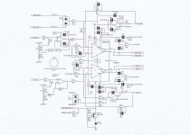
Here is Arcam's way - maybe the best way")
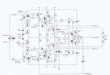
The best way is to buffer the input, invert, and feed the inverting input of the LM4702. I used the OPA2604 -- it really sounds nice. I had some boards made up for a LM4702 project which was published in AudioXpress and found that I could fit the OPA2604 and associated components in the space of the rather large capacitor I was using.
I have two pairs of Exicon 10P16/10N16 lateral mosfets I would like to use with a LM4702. I plan a 2K preset across the gates for bias adj and 220R gate stoppers. Anything else I should bear in mind.
Use a 1k potentiometer between the SINK and SOURCE outputs of the LM4702so that you can set the bias, AND a 47k resistor from SINK to ground. Bias for about 120mA.
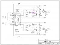
The simpler the better. Have been using this circuit for over 5 years and sounds outrageous. I use two 4702s....one for for each channel and ground the unused inputs on the other unused channel. Dual mono is always better. I use a single power transformer for each channel but rectify it twice so I have a separate power supply for the 4702 and for the output mosfet stage....very important for great sound. I use nude Vishay resistors, damped heatsinks, damped soft recovery diodes, binding post bypass system, nude Blackgate N in feedback with nude modded Wima bypass and modified Wima Bypasses on all power supplies. You do not need the zobel network or inductor on the output if you are driving non capacitive normal speakers. Driving electrostats will require a zobel and maybe the inductor.
Attachments
How do you attach a picture as a thumbnail?
Hi Ric,
Since you attached a non-image file, which is a pdf, forum software doesn't know how to preview it as a thumbnail.
Thanks for schematic but I want build a bipolar/bjt version.
LME49811 is LM4702's mono version btw.
Regards.
Help request
Hi,
I'm new at forum.I was interested to make chip amps in past.But i had a break for a while diyaudio.Now I plan to use the materials at home and make a new amp.
I want to make LM4702BTA chip amp with STD03N-STD03P.
My first questions :
My best
Hi,
I'm new at forum.I was interested to make chip amps in past.But i had a break for a while diyaudio.Now I plan to use the materials at home and make a new amp.
I want to make LM4702BTA chip amp with STD03N-STD03P.
My first questions :
- Do you have LTspice simulation models of LM4702BTA and STD03 ?
- Do you have KiCad models of LM4702BTA and STD03 ?
- I'm looking for STD03N Y model?How can i find Y models?
My best
Last edited:
LM4702 model is no longer on TI's website, its's a pity that the product is discontinued but the world is going Class-D. The SPICE model which TI had on their website didn't help with compensation.
In any event, it's very easy to implement an STD03N/P design with the chip. Instead of a VBE multiplier, use a 250R potentiometer between the Cathode of the N-device diode and the Anode of the P-Device's diodes.
Compensation capacitor of 30pF from the comp pin to the "Sink" output of the 4702.
The difference between the STD03N "O" and "Y" models is that the "BF" the "Y" devices have current gain of 8,000 to 20,000... the "O" devices 5,000 to 12,000.
I always recommend two filters on the inputs to our audio equipment.
A High Pass filter to attenuate ultra low frequencies and block DC offsets.
A Low Pass filter to attenuate RF interference.
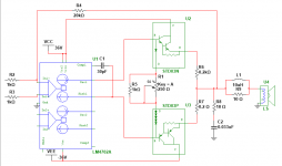
The output needs and output Zobel, R8 + C2
The output also benefits from attaching the Output inductor with it's damping resistor, L1||R9. This allows one to attach unknown cable and unknown speaker, without risk of destroying the amplifier due to reactive load induced oscillation.
I recommend a small alteration to the output inductor.
Make L1= 0.7uH to 2uH & R9= 10r||10r= 5r
Add an extra R+C across the amplifier's speaker output terminals. R=10r||10r = 5r, C= 100nF.
This gives a Pi version of the Thiele output network where two Zobels are fitted onto the output inductor.
A High Pass filter to attenuate ultra low frequencies and block DC offsets.
A Low Pass filter to attenuate RF interference.
The output needs and output Zobel, R8 + C2
The output also benefits from attaching the Output inductor with it's damping resistor, L1||R9. This allows one to attach unknown cable and unknown speaker, without risk of destroying the amplifier due to reactive load induced oscillation.
I recommend a small alteration to the output inductor.
Make L1= 0.7uH to 2uH & R9= 10r||10r= 5r
Add an extra R+C across the amplifier's speaker output terminals. R=10r||10r = 5r, C= 100nF.
This gives a Pi version of the Thiele output network where two Zobels are fitted onto the output inductor.
Last edited:
Thank you for circuit .Please let me ask for these questions:
There is no need to use input cap ? And exactly what is the function of the inductor on output way ?
I just showed the output stage -- you can follow the data sheet example, or do something a bit fancier, such as using opamp buffer and inverter, plus servo.
- Status
- This old topic is closed. If you want to reopen this topic, contact a moderator using the "Report Post" button.
- Home
- Amplifiers
- Chip Amps
- Lm4702