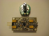
This is something I use everyday that sounds just right for me, but I am trying to make things a bit tidier so I redesigned the board from scratch. I plan to use LM4562 in a can which allegedly sounds better. Before it goes into homebrew pcb production, I would like to get the community's view of this design, in case I made some stupid mistakes. If someone finds it useful, I can also make eagle files available for everyone.
Attachments
It looks like you are using +/-12Vdc power supply rails and a stage gain of 10x. What impedance of headphones or IEMs are you using the circuit with?
One suggestion for driving lower impedance phones would be to substitute a 70mA/channel NJM4556, like used in the O2 headphone amp, in place of the 20mA/channel LM4562, then drop the output resistors to 10 ohms or so.
http://www.google.com/url?sa=t&rct=j&q=njm4556&source=web&cd=4&ved=0CDcQFjAD&url=http%3A%2F%2Fwww.bdent.com%2Fv%2Fvspfiles%2Fdownloadables%2FNJM4556S.pdf&ei=byI9T5XsG4nZ0QH0nJXMBw&usg=AFQjCNHdR3gh-qbZyPfLIiwsQYdcxLoy5w&cad=rja (NJM4556 datasheet)
The pin-out on the two chips are the same so you could just swap back and forth. You could even socket those 100R output resistors with 0.1 headers.
Here is a TO-99 to DIP adapter so you could still use that metal can version of the LM4562 with the DIP socket:
http://cimarrontechnology.com/to-99to8-pindipadapterpn020601-1.aspx
The metal cans really are supposed to sound better.") I saw an post or article somewhere along the way, a few years ago, from someone who worked at National saying the group was going to look into why that was, but about that time National disbanded the audio group.
I saw an post or article somewhere along the way, a few years ago, from someone who worked at National saying the group was going to look into why that was, but about that time National disbanded the audio group.
One suggestion for driving lower impedance phones would be to substitute a 70mA/channel NJM4556, like used in the O2 headphone amp, in place of the 20mA/channel LM4562, then drop the output resistors to 10 ohms or so.
http://www.google.com/url?sa=t&rct=j&q=njm4556&source=web&cd=4&ved=0CDcQFjAD&url=http%3A%2F%2Fwww.bdent.com%2Fv%2Fvspfiles%2Fdownloadables%2FNJM4556S.pdf&ei=byI9T5XsG4nZ0QH0nJXMBw&usg=AFQjCNHdR3gh-qbZyPfLIiwsQYdcxLoy5w&cad=rja (NJM4556 datasheet)
The pin-out on the two chips are the same so you could just swap back and forth. You could even socket those 100R output resistors with 0.1 headers.
Here is a TO-99 to DIP adapter so you could still use that metal can version of the LM4562 with the DIP socket:
http://cimarrontechnology.com/to-99to8-pindipadapterpn020601-1.aspx
The metal cans really are supposed to sound better.
I saw an post or article somewhere along the way, a few years ago, from someone who worked at National saying the group was going to look into why that was, but about that time National disbanded the audio group.
Last edited:
Probably inductive coupling between signal and rails on the DIP8 package with standard pinout (remember, class B currents and stuff). Seems to be a significant problem when moving into RF territory, with special "low distortion" pinouts available as a consequence.The metal cans really are supposed to sound better.
Looking at the circuit, 100 ohms of R_out is a little high for most anything save for 600 ohm cans. And yes, LM4562s aren't super high current, though with a NE5532 commonly doing a fairly nice job "barefoot", the '4562 certainly shouldn't do too badly either. (I'd still prefer a buffered arrangement, but space is obviously tight here.)
Board wise, I might look into making xmfr secondary side loop area a bit smaller (maybe move the xmfr to one side), but other than that it looks pretty good to me for a single-sided board. If you can find the space, a few small caps for RF suppression at the rectifier might not be that bad an idea either.
Last edited:
Just a thought... the opamp feedback network is DC coupled and of unequal impedance to the input network. Have you measured for real what the DC offset is ? The LM4562 has fairly low input bias currents, a 5532 would certainly have a significant offset many 10's or 100's of millivolts which isn't good. Any bjt opamp will have this issue used like this.
Why not at least include space for caps in the feedback return. You can always link them out if not needed. and perhaps look at equalising the networks. Noise isn't such an issue in reality.
Why not at least include space for caps in the feedback return. You can always link them out if not needed. and perhaps look at equalising the networks. Noise isn't such an issue in reality.
Well spotted, Mooly... that 100k pot is a little on the high side, too. I'd go down all the way to 10k if that's not an issue in terms of sources. Given the low Vnoise level of a 4562, that would drop noise by (up to) almost 10 dB... nothing to sneeze at for sure.
Last edited:
It looks like you are using +/-12Vdc power supply rails and a stage gain of 10x. What impedance of headphones or IEMs are you using the circuit with?
One suggestion for driving lower impedance phones would be to substitute a 70mA/channel NJM4556, like used in the O2 headphone amp, in place of the 20mA/channel LM4562, then drop the output resistors to 10 ohms or so.
http://www.google.com/url?sa=t&rct=j&q=njm4556&source=web&cd=4&ved=0CDcQFjAD&url=http%3A%2F%2Fwww.bdent.com%2Fv%2Fvspfiles%2Fdownloadables%2FNJM4556S.pdf&ei=byI9T5XsG4nZ0QH0nJXMBw&usg=AFQjCNHdR3gh-qbZyPfLIiwsQYdcxLoy5w&cad=rja (NJM4556 datasheet)
The pin-out on the two chips are the same so you could just swap back and forth. You could even socket those 100R output resistors with 0.1 headers.
Here is a TO-99 to DIP adapter so you could still use that metal can version of the LM4562 with the DIP socket:
TO-99 to 8-pin DIP Adapter (p/n 020601B)
NJM4556 - isn't it supposed to be inferior to LM4562 (LME49720)?
I will be using GS-1000 and FA-003, hence 100ohm at the output. Board will be fitted with dil8 socket and with little leg bending, it should take cans as well as dip8s.
LM4562 is good, in fact it's better than the venerable NE5532 for driving difficult 600 Ohm loads, but even with your 100 Ohms series build-out resistor, GS-1000 would look like 132 Ohms to your opamp, and very few small signal opamps tend to cope well with that kind of load.
Choosing another opamp designed for heavier loads like the OPA551 should work pretty well with the kind of load you are giving it, or if money is no subject, and you want the lowest distortion/noise from just LM4562, just parallel them up and sum the outputs with 1 ohm resistors. 3x LM4562 per channel should make them quite comfortable driving the headphones in series with the 100 ohm resistor.
NJM4556 is nice because it has moderately good distortion performance for cheap, and is rather good at driving heavy loads. This works out nicely in an output stage as you are not using it for gain.
Thanks for a great idea! Money is never an object when samples are used, so I will try to parallel them as you suggested
I have built it already with single LME49720 in TO-99 and it seems to work ok with FA-003 and 100ohm in series. It does get a bit warm at around 40deg C, so having a can package probably helps with dissipation. Output DC offsets are 16 and 24mV on respective channels.
I have built it already with single LME49720 in TO-99 and it seems to work ok with FA-003 and 100ohm in series. It does get a bit warm at around 40deg C, so having a can package probably helps with dissipation. Output DC offsets are 16 and 24mV on respective channels.
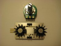
Before it goes into homebrew pcb production, I would like to get the community's view of this design, in case I made some stupid mistakes. If someone finds it useful, I can also make eagle files available for everyone.
If you are out asking for help, it's the least you can do to upload the Eagle files in return. It might help someone else.
Nothing especially dramatic about a non-inverting op amp powered by LM317/337s, if you accept that op amps are capable of driving headphones, and that the LM317/337 sound fine, off you go...
As others have pointed out there are a couple of eye-openers on the schematic, the biggest is the 1uF caps in front of the regulators. That's just not going to work, the ripple will be so large that the regulators are going to suffer dropouts.
Next is the 100 ohm resistor on the op amp output in series with the load. It's a valid approach and serves to linearize the gain, but generally frowned upon nonetheless because the output impedance driving the headphones is now a high 100 ohms.
Last there's that 100kohm volume pot. Been there, done that, and frankly any non-Jfet input op amp is going to give you grief. 20k is a better target, since at normal volume levels the output impedance of the volume pot is down under 1k which balances the inverting op amp input reasonably well under audio frequencies anyway. Most people put 1k in series after the volume pot to keep the impedance looking out of the noninverting input slightly more constant, and also allow the little input filter cap to do its work even at very low volume settings.
You are knocking on the open door - as I said in the first post, I will gladly share eagle files if there's interest and after they are finished. And yes, filter caps and pot size were changed already...
- Status
- This old topic is closed. If you want to reopen this topic, contact a moderator using the "Report Post" button.
- Home
- Amplifiers
- Headphone Systems
- LM4562 based headphone amp