Thanks for all the replies.
I used Audacity to make a 150Hz sine wave. The voltage at the soundcard line out was 1.2V and after the amp it was 29.6V. Also I checked all the parts again and they are correct.
Thanks
I used Audacity to make a 150Hz sine wave. The voltage at the soundcard line out was 1.2V and after the amp it was 29.6V. Also I checked all the parts again and they are correct.
What does C3 do? I have a 100uF one would that work?C3 is important also. If you have another one (even larger) try it.
Thanks
C3 is the DC blocking capacitor in the Negative FeedBack loop (NFB).
It also rolls off the gain of the amplifier at low frequencies.
This is half of what is needed for an AC coupled amplifier.
At present this is a mixed AC & DC coupled amplifier, because the DC blocking capacitor has been omitted at the input after the volume control.
This gives rise to excessive and variable output offset.
I have a 100uF one would that work?
Yes, better than this ridiculous 10uF
220uf is often seen in that position...
They must all be wrong then.
You might want to remember what this amp is for - guitar. Guitar amps are NOT audiophile equipment.
Actually, that 'ridiculous' 10uF is what National recommends for this chipamp
Last edited:
I used Audacity to make a 150Hz sine wave. The voltage at the soundcard line out was 1.2V and after the amp it was 29.6V. Also I checked all the parts again and they are correct.
29,6 V is more than the 8-10 V you mentioned earlier and might already be where your amp clips. 29,6 V would be ~110 W into 8 Ohm. Try a different speaker for more SPL.
Yes, a cheap chip amp.
An electric guitar's lowest note is ~80 Hz. 10 µF and 1k give ~16 Hz. Five times lower than the lowest note is quite acceptable.
It is not as bad as you think. 10 uF will give you 16 Hz and this is in fact quite alright for a guitar amp.Yes, better than this ridiculous 10uF
EDIT: Oops, the poster above has already enlightened you.
no, you forgot to read that the RC time constant is what should be taken into account.220uf is often seen in that position...
They must all be wrong then.
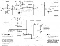
no the pre-amp section is the typical "box of tricks" that musicians use to shape the music into a form they and their audience like.Regarding the preamp, if I build the one below without the power amp section will it have enough gain or should i build it with the power amp.
Note the very low input impedance of the first inverting opamp. This must be fed from a pre-preamp that can drive this low impedance and all the cable between the pre-pre and the box of tricks.
The guitar pre-pre is there to magnify slightly (or more than slightly) and prepare the signal to drive long cables and any sensible Rin (Zin) that follows.
This pre-pre must be in the guitar or in the cable plug that exits the guitar or on the Guitarist. Did you read that article on the jFET pre? All the info you need was in that excellent link so kindly proffered by a Member. Do him the courtesy of reading the article.
Member
Joined 2009
Paid Member
could be completely off base - but I have read reports of people finding themselves in the possession of chip amps with problems because they got Chines fake parts. I don't know if this is old news but I've read of multiple issues including the extreme case of a plastic package with pins and labels and nothing inside it but more plastic !
I dont think that it could be a fake because i got the IC form Farnell. I dont think they would be selling fakes.
Yes, since you said this:
there is little chance the chip is fake.The voltage at the soundcard line out was 1.2V and after the amp it was 29.6V
Any progress on the preamp?
Hi,
I have been following this tread and in one of the tread you mentioned that you used the output from your computer and also the output from your Ipod that put 1.2 volts. I think that 1.2 volts should almost make the LM3886 full blast. I built my amplifier using the same schematic and I did have any problem. I just followed the schematic wiring with no problems. I think that you should go back to your built and check the wiring. Something is wrong in your amplifier wiring.
I have been following this tread and in one of the tread you mentioned that you used the output from your computer and also the output from your Ipod that put 1.2 volts. I think that 1.2 volts should almost make the LM3886 full blast. I built my amplifier using the same schematic and I did have any problem. I just followed the schematic wiring with no problems. I think that you should go back to your built and check the wiring. Something is wrong in your amplifier wiring.
- Status
- This old topic is closed. If you want to reopen this topic, contact a moderator using the "Report Post" button.
- Home
- Amplifiers
- Chip Amps
- LM3886 very quiet