Depends on what you consider normal. Also depends on the supply voltage."The heatsinks are too small" There's no way those are too small for normal listening levels.
40 VCT will result in ~±27 V rectified. At that voltage the LM3886 will dissipate about 3 W at idle. That alone will get the heat sinks to 42 ºC assuming 25 ºC ambient and that the heat sinks are Boyd 6400BG. The thermal resistance of the heat sink is 5.7 K/W.
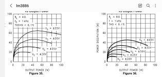
The amp will overheat if it delivers more than about 5 W into 8 Ω. See figs 35-36 in the LM3886 data sheet:
As you can see, about 20 W will be dissipated in the LM3886 at that supply voltage even at that low output power. That'll result in a heat sink temperature of 139 ºC and a chip temperature well about 150 ºC.
If you never push the LM3886 out of class A operation, you'll be fine. But personally I would add a little Noctua fan.
Tom

Hey, actual engineering. Nice. I'm running +/- 25 Volts and a single 5" x 7" of thin aluminum sheet that is the top panel for a plastic Radio Shack project box as the heat sink for a stereo pair in that box without problems. Likely my 8 ohm speakers, lack of sustained full volume club music and the low power supply contribute to my amp chips working fine for the past 14 years. Hopefully the OP gets the diode bridge corrected in time to turn in the senior project.
You have designed floating ground power supply. Full floating ground can supply only one channel. What places the output to be center to Vcc Vss is R3. It should be referenced to two resistors from the rails to create a floating center point to become the ground.
The second channel needs seperate rectifiers, capacitors.
You can use my semi floating supply for 2 channels.
https://www.diyaudio.com/community/threads/semi-floating-split-supply-vs-standard-psu.403257/
The second channel needs seperate rectifiers, capacitors.
You can use my semi floating supply for 2 channels.
https://www.diyaudio.com/community/threads/semi-floating-split-supply-vs-standard-psu.403257/
A piece of sheet aluminum can have pretty decent thermal performance. There're some details here: https://electronics.stackexchange.c...the-thermal-resistance-of-aluminum-flat-stock
Tom
Tom
The DS gives the maximum operating Tc, case temperature, on the graph bellow.

Foe example. You have +/-35V supply and 8ohms load. The graph shows the maximum dissipation is 30W and maximum operating case temperature is 114°C. If you apply an isolator and grease, it will ask 1°C/W difference which makes the temperature of the heatsink to be max 114-30=84°C.
The graph bellow says with +/-35v, the maximum dissipation occurs at 30W output and will disspate about 34W, this why better limit the heatsink temperature to 70°C.
The way the heatsink is placed is an important factor. If the under part is open to invite new fresh air to circulate or closed, makes a great difference. You need to try out in the enclosure.
Attachments
Last edited:
So, I redid the power supply schematic using many of the forum suggestions. I believe this 4 diode rectifier should work the way I intend it to but, whenever I try to run the transient simulation with the command text included in the image, I get an error saying my time step is too small. Does anyone know why this would be the case?
The power supply simulation works find if not connected to my amplifier circuit, but as soon as I connect them the simulation takes way too long and I get an error before even reaching a couple of ms.
Also, the heat sinks are 2485-RA-T2X-64E-ND's, and the goal is to get an output of 25W. I need 20V (positive and negative) and about 3 amps to get the values (according to the equations provided at the bottom of the datasheet).
Last edited:
@HAYK The ratio you see on the drawing is in Henries not turns.
Is this what you mean for the simulation command window? It didn't work, i have been told to start my transient reading later than 0 and have noticed that LTSpice is still very slow to start up and get to the initial reading point.
Also, what resistance value should I add to the primary and secondary sides?
Once again, as I pointed out before, you have the "mute" pin(8) pulled low with a ground connection...I'm not sure if the Spice model of the LM3886 works exactly the same as the real one, but if it does, pin(8) must be pulled high through a current limiting resistor or it will remain in "mute" mode, and the amp will not work.
Mike
Mike
Once again, as I pointed out before, you have the "mute" pin(8) pulled low with a ground connection...I'm not sure if the Spice model of the LM3886 works exactly the same as the real one, but if it does, pin(8) must be pulled high through a current limiting resistor or it will remain in "mute" mode, and the amp will not work.
Mike
The spice model I'm using definitely isn't perfect. These are the results for the amplifier circuit with some basic voltage sources.
And this is what I get when the mute pin is connected to my negative rail (with 40uA flowing out of the mute pin). If I leave the mute pin disconnected the circuit also amplifies. So I guess whoever made this model must've misread the datasheet.
The current of the rails are not implemented in the model. You need to add a pair of output transistors 5200, 1943 with bases linked to output and 100 ohm resistor between basses and linked emitters.
Your 2x18v ac will sag to about 21v which is suitable for 4 ohms load to output 40w.
Your 2x18v ac will sag to about 21v which is suitable for 4 ohms load to output 40w.
Attachments

Last edited:
- Home
- Amplifiers
- Chip Amps
- LM3886 Stereo Amplifier and Power Supply Design