How did you measure the increase in apparent gain @ 60kHz?
Measure the input signal and a reduced version (a pair of resistors) of the output signal using the same voltmeter, at the same setting, at both ends.
Now change the test frequency and compare the input to output voltages.
Repeat at a variety of frequencies.
Does the gain really increase by +6dB above 20kHz?
The amp never gets hot, even when I push it as I have a large heatsink and power supply voltage limits output to 30W per channel.
Note that the testing I did above with the function generator was with nothing connected on the output. Do I need a load for this type of test?
The amount of heat is mostly reliant on the load.
It may be good to measure the amplifier "in action" instead of (or in addition to) measuring it while it is doing no significant work.
A cleaner power circuit is less work for the amplifier and this may provide the tolerances to make a more powerful amplifier as well.
before I bought a second hand bench meter I too did not have a true rms voltmeter.I don't have a multimeter that can do RMS.
But, by adding an accurate attenuator in front of the amplifier and adjusting, precisely so that input voltage = output voltage, you can "compare" input and output voltages over a massive range of frequencies that are way outside the effective range of the multimeter. I have done 20Hz to 60kHz with a cheap meter that has a 2000 count 200mVac scale. It was not good at very low frequencies. It was useless at <10Hz. The bench meter is a completely different animal 50000 count and measures from <1Hz to >1MHz.
Late to this.
I'm now building an amp with LM3886, too, and would like to ask, is DC servo necessary for this chip? How often does it "drift away" and kill itself and speakers? The cap in the feedback circuit is enough or not?
Or, DC servo is a more refined way to deal with the offset issue than only a cap?
I'm now building an amp with LM3886, too, and would like to ask, is DC servo necessary for this chip? How often does it "drift away" and kill itself and speakers? The cap in the feedback circuit is enough or not?
Or, DC servo is a more refined way to deal with the offset issue than only a cap?
A DC servo is not necessary if you use an input capacitor as well as a feedback capacitor. Some people believe that using capacitors to reduce offset does not sound as good as a DC coupled amp. I haven't built a comparable AC coupled amp to compare, so I can't say for sure, but I really enjoy the sound of my design.
Here are the Eagle 5 schematic and layout I used if anyone wants to make their own.
Some suggestions I was given:
- Add pads for a resistor between the input signal ground and the main ground so a jumper or resistor can be used (in case there is ground loop hum, I certainly don't have any with any of my sources)
- Add pads for smaller main capacitors
- Double the pin spacing of the connectors for more commonly available ones to be used
Attachments
No problem, but if, as your post suggests, you have a feedback capacitor but not an input capacitor, you need to add an input capacitor.
If I can assure there'd never be DC at the input, do I still need an input cap?
The datasheet of LM3886 doesn't include that (figure 1). My setup is pretty much like that in this regard - with a volume pot in front (and my upstream pre amp is transformer coupled).
I managed to get it running last night and it seemed to work OK without the input cap. I got about 9mV output offset and it's not changed by the volume pot setting.
Any pitfall?
Last edited:
are you sure? Check again.I got about 9mV output offset and it's not changed by the volume pot setting.
If your source has a DC blocking capacitor on it's output then you don't need a second DC blocking capacitor at the input of the receiver.
An input capacitor is just a safety device. If you never want to worry about DC, then use it. Otherwise, you need to consider testing the DC offset of every source you connect.
That's why I chose to go with a servo and a DC detection/protection circuit on the output. I don't need to worry about it (and the DC detection/protection circuit has already saved my speakers).
That's why I chose to go with a servo and a DC detection/protection circuit on the output. I don't need to worry about it (and the DC detection/protection circuit has already saved my speakers).
I agree.That's why I chose to go with a servo and a DC detection/protection circuit on the output.
A DC coupled amplifier should have both DC servo and DC detection activating speaker protection.
I don't understand your reasoning.the output of the upstream (my pre amp) is transformer coupled, so the (+) input of the chip is pulled to ground by that very low DCR winding. The (relatively high impedance) volume pot can't affect it.
Output offset voltage is affected by the imbalanced input voltages (between + and -). And the input offset voltage is set by input offset current of the 2 inputs on the impedance they see. So the impedance changes, voltage changes. This is by the datasheet, or what I've read. Correct me if something wrong.
Now my + input is gounded (by the upstream trafo's winding), so the volume pot can't change that low impedance, thus no change to the input offset.
Now my + input is gounded (by the upstream trafo's winding), so the volume pot can't change that low impedance, thus no change to the input offset.
I don't know how you have wired up your volume adjustment pot.
If it is done as usual, it presents a variable resistance to the receiver.
This variable resistance will develop a variable voltage and that in turn affects output offset.
The transformer before the pot does not affect what the pot presents to the amp.
If it is done as usual, it presents a variable resistance to the receiver.
This variable resistance will develop a variable voltage and that in turn affects output offset.
The transformer before the pot does not affect what the pot presents to the amp.
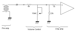
Let's assume the DCR = 10r0. The resistance seen by +IN is
1k0 + [ 22k // 10kApot // {5k + dcr} ]
If 10kpot is set to 10k then +IN sees ~3898r (maximum volume = -4.75dB)
If 10kpot is set to 0k001 then +IN sees 1001r (minimum volume = -74dB)
I would suggest that -IN should see ~2k5, to minimise the maximum input offset resistance to <1k5
1k0 + [ 22k // 10kApot // {5k + dcr} ]
If 10kpot is set to 10k then +IN sees ~3898r (maximum volume = -4.75dB)
If 10kpot is set to 0k001 then +IN sees 1001r (minimum volume = -74dB)
I would suggest that -IN should see ~2k5, to minimise the maximum input offset resistance to <1k5
Thank you Andrew.
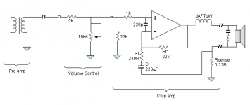
Previously, I set the feedback resistance as 91k / 1k Ohm as posted in another thread.
I set it with mixed current and voltage feedback, so the combination of resistors is somewhat unusual.
It had 9mV offset with that setup as mentioned earlier. And then I modded with smaller ones of 22k / 249R as attached below. The offset voltages are now 1.7mV and 2.3mV (2CH). Turning the pot, one becomes 1.9mV, and the other is unchanged 2.3mV (??) Pretty good I'd say At least far better than my expectation. (This amp only serves a pair of big dumb pro woofers which can take a lot of abuse, and under 240Hz)
Now the -IN sees 22k, the 249R is blocked by the cap and theoretically open at DC. I have trouble to make the resistance any lower. The Ri would be VERY small to maintain the output impedance I need, thus the VERY BIG Ci to get proper LF limit.
I don't mind using big electrolytic caps in the signal chain, but they are too bulky to fit in the small PCB now...
Oops, this is OT a lot. I'd stop here.
Previously, I set the feedback resistance as 91k / 1k Ohm as posted in another thread.
I set it with mixed current and voltage feedback, so the combination of resistors is somewhat unusual.
It had 9mV offset with that setup as mentioned earlier. And then I modded with smaller ones of 22k / 249R as attached below. The offset voltages are now 1.7mV and 2.3mV (2CH). Turning the pot, one becomes 1.9mV, and the other is unchanged 2.3mV (??) Pretty good I'd say
At least far better than my expectation. (This amp only serves a pair of big dumb pro woofers which can take a lot of abuse, and under 240Hz)Now the -IN sees 22k, the 249R is blocked by the cap and theoretically open at DC. I have trouble to make the resistance any lower. The Ri would be VERY small to maintain the output impedance I need, thus the VERY BIG Ci to get proper LF limit.
I don't mind using big electrolytic caps in the signal chain, but they are too bulky to fit in the small PCB now...
Oops, this is OT a lot. I'd stop here.
Attachments
Last edited:
- Status
- This old topic is closed. If you want to reopen this topic, contact a moderator using the "Report Post" button.
- Home
- Amplifiers
- Chip Amps
- LM3886 Servo Design