Zener 16V is for turn on delay but your PSU voltage with 2x15vac is too low, just use 5V6 zener instead 16V and that will unmute LM3886.
Maybe a silly question but why did you use a zener diode instead of a regular resistor for the mute circuit?
Oscillation help
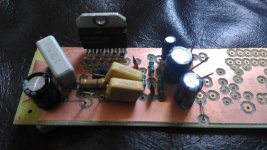
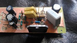
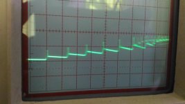
I have build one of the stereo boards with the addition of a ground plane, from the gerbers posted in this thread but the chip oscillates badly with load or no load. Ground plane is on the bottom, it was double sided board so top does not connec to anything.
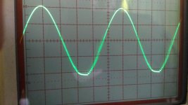
See attached for 1KHz input signal and associated oscillation. Used parts I had lying around, all values are correct but some of the footprints didn't match, the Zener is 15V. Can anyone please help?
I have build one of the stereo boards with the addition of a ground plane, from the gerbers posted in this thread but the chip oscillates badly with load or no load. Ground plane is on the bottom, it was double sided board so top does not connec to anything.
See attached for 1KHz input signal and associated oscillation. Used parts I had lying around, all values are correct but some of the footprints didn't match, the Zener is 15V. Can anyone please help?
Attachments
Last edited:
I have build one of the stereo boards with the addition of a ground plane, from the gerbers posted in this thread but the chip oscillates badly with load or no load. Ground plane is on the bottom, it was double sided board so top does not connec to anything.
See attached for 1KHz input signal and associated oscillation. Used parts I had lying around, all values are correct but some of the footprints didn't match, the Zener is 15V. Can anyone please help?
is this the original apex lm3886? zobel appears to be there.
Last edited:
parasitic capacitances ?Prasi it is the same board you build based on the PCB by Bimo, but I added a GND plane.
To design a ground plane one must know how to design a ground plane.
That is not the same as adding a top surface copper layer.
I honestly don't think it would be the ground plane, especially since in this case all it really did was to thicken out the 0V track to the outer edge of the board where all the 0V connections lay. It didn't really add any extra copper near to other connections as the board density was already quite high. Basically the majority of the PCB didn't actually change at all.
have you double checked the values of res?
the jumper near ic pins is precariously close to 'spk out'.
also check if both 1uf caps are connected to ground.
zener 15v is ok. whats your supply voltage?
before giving up all hope, why not populate other channel and see if problem persists.
one more thing, continuity check from top of a soldered pin to the top of all adjacent soldered pins that are supposed to connect with it. this will tell you if there is a cold joint.
you may have already done this, but just want to ensure no stones left unturned.
my 2c.
I have few extra pcbs and all components of the Apex Super GC, if you want to take a stab at that. but its not tested yet.
reg
Prasi
Do you have a dual voltage power supply?I have built one channel exactly as it is on APEX's schematic, I am testing it from a regulated DC bench supply. The 4r7 and 220n zobel is on the board.
Prasi, have pretty much done all of those but will check some more joints. Have done the main ones such as fb resistor etc. Thanks for the offer but hoping to get this running at the moment.
Peranders, no dual supply but have made an 0V by bridging. However I have a little 1A mini dual supply and it was exactly the same.
I have tried on a range of voltages between 20-35V per rail, same results.
Thanks all.
Peranders, no dual supply but have made an 0V by bridging. However I have a little 1A mini dual supply and it was exactly the same.
I have tried on a range of voltages between 20-35V per rail, same results.
Thanks all.
Thanks for the replies, yes I have two separate supplies in series as in - (+-) + to create a duel supply. Yes I am testing with a heatsink attached and between 20-35V per rail.
The mute circuit is the original design with the unmute at power on delay with diode.
PSU's are just bench supplies.
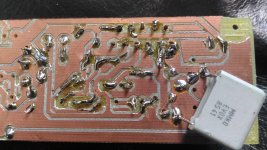
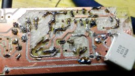
The ground plane is just a polygon fill of space around the board on the bottom connected to 0V. I forgot to remove islands though so there are a few bits of floating copper which you can see the in the photos.
The mute circuit is the original design with the unmute at power on delay with diode.
PSU's are just bench supplies.
The ground plane is just a polygon fill of space around the board on the bottom connected to 0V. I forgot to remove islands though so there are a few bits of floating copper which you can see the in the photos.
some slide mods maybe ?
hallo . Did you ever try LM4562 instesd of OPA2134P (replacing 7818/7918 with 7815/7915)? If yes, the sound quality get improoved ?
Mr. Mile Here is the layout for Super Gainclone. Is it ok?
regards
Prasi
hallo . Did you ever try LM4562 instesd of OPA2134P (replacing 7818/7918 with 7815/7915)? If yes, the sound quality get improoved ?
Hi all,
Have finally got round to taking a dremel to the board and taking off the copper islands. Some parts got caught a bit but none were severed so went over them with solder. I've checked there is no connection between the top remaining copper and any component connections.
I have put some red squiggles over suspect parts that are actually okay which I've checked.
The amp STILL oscillates just the same with no load!!
Any suggestions before I try another chip?
Thanks
Attachments
- Home
- Amplifiers
- Chip Amps
- LM3886 Schematics + PCB