") Thanks!
Thanks!Ah, you mean applying a small (a few mV) variable voltage at the inverting pin of the LM3886's ?
That sounds good for the non-inverting stages, but what for the others?
I was thinking on building 4 identical stages, non-inverting, and adding a inverting circuit with an op-amp to excite two of them, so your idea can be suitable.
But do you think it is going to behave well as the offset changes with temperature?
Thanks!
ssanmor,
I'm now stuffing a new PCB I made up, doing what you've talked about. I've got on one board that's about 2 x 7 inches, 4-LM3886 devices, all running non-inverted (this gives better performance: you don't have the feed back 'bucking' the source that's driving the - input).
I based it on the schematic in the application link that AudioFreak listed above, but only using the top half of their schematic--that is, the non-inverted portion. I repeated the upper non-inverted portion for the 'bottom' half. Each output pair drives a resistor/inductor and then the load.
Next, I split the single input buffer op-amp into two, using one to drive the upper non-inverted pair with a non-inverted input signal, and the second to drive the bottom half with the inverted input. That is, each input polarity is running into a non-inverted AD8610.
12V regulation is provided for the input buffers devices separately from the regulated supplies for the LF411CN used in the DC servo circuit. (Instead of using two op-amps, I've also set it up to use a Jensen input transformer, with one secondary leg driving the + LM3886 pair and the negative leg the other LM3886 pair; it's always fun to compare!)
This means the whole amplifer, while bridged, is fully balanced and non-inverted. I designed the boards so that multiple units could be paralled to even further increase the low impedance drive capability. I was thinking that 2 or 3 boards, each with a two pair (4-LM3886), should drive a 2 ohm load with around 700 watts. (4 bridged units give around 150 to 200 watts into 8 ohms and 300-400 watts into 4 ohms; so 8 units should handle a 2 ohm load with 600 to 800 watts, depending upon the power supply and heat sinking.)
Hopefully, I'll have one board running by this weekend and if it tests out OK, I'll plug it into my system.
LM3886 parallel use
Thanks for the explanation. Could you send me a schematic of your whole amplifier for clarification?
I am also going to do some tests this week, I will tell you how it goes.
You can send the sch. to ssm07@tid.es or ssanmor@canal21.com
Thanks!!
Thanks for the explanation. Could you send me a schematic of your whole amplifier for clarification?
I am also going to do some tests this week, I will tell you how it goes.
You can send the sch. to ssm07@tid.es or ssanmor@canal21.com
Thanks!!
rljones,
I have been working on this very same design but have had some problems. I am unfamiliar with the dc servos and their function. The amp I built also runs way too hot. Could you e-mail me your schematics and pcb if possible.
My e-mail is bopppe069@uwsp.edu
Thank you in advance,
Opie
I have been working on this very same design but have had some problems. I am unfamiliar with the dc servos and their function. The amp I built also runs way too hot. Could you e-mail me your schematics and pcb if possible.
My e-mail is bopppe069@uwsp.edu
Thank you in advance,
Opie
LM3886 parallel-bridge
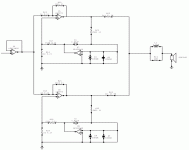
My idea is this (I will try to explain it as clear as I can):
I am going to use four identical non-inverting amplifiers like the one shown in this picture. The output R in parallel with L is substituted by a 0.1Ohm/5W resistor, (all picked by-hand to minimize differences between them).
Then two of them are excited by the direct input signal from my preamplifier (with a gain=1 buffer). This signal is inverted by an inverting opamp with gain=1 and then drives the other two power stages.
The outputs of the two top stages are connected together and to the + terminal of the speaker; The outputs of the bottom stages are also connected together and to the - terminal of the speaker.
All the gain resistors are also picked by hand to match them within 0.1%
As you can note, I don't use servos. The stages are AC coupled, so they don't amplify the DC offset from the preamplifiers.
Does this set-up have any chance of working well? If you don't think so sincerely, please send suggestions.
Thanks!
Attachments
Re: LM3886 parallel-bridge
Didn't that App note from National warn about trying to do this without the servo?
If the two amps have, say, a 100mV difference in offset, this would be 0.5 amps through the balancing resistors (100 mV / (0.1+0.1))!
But it does not help with the DC offset from the amplifiers themselves. The 0.1 ohm resistors you're proposing may be too small to keep the two amps from "arguing" as Nelson says.ssanmor said:The stages are AC coupled, so they don't amplify the DC offset from the preamplifiers.
Didn't that App note from National warn about trying to do this without the servo?
If the two amps have, say, a 100mV difference in offset, this would be 0.5 amps through the balancing resistors (100 mV / (0.1+0.1))!
- Status
- This old topic is closed. If you want to reopen this topic, contact a moderator using the "Report Post" button.
- Home
- Amplifiers
- Chip Amps
- LM3886 Parallel Use