12mVdc of output offset for a complete sweep of the vol pot is considerably better than the 100mV to 200mV of offset changes I have seen in other Direct Coupled implementations.
Cvp,
do not become complacent.
You must ensure that faults elsewhere do not damage your speakers.
Detect DC and correct excessive DC and isolate if outside the correction range is a minimum requirement for a DC coupled implementation.
Cvp,
do not become complacent.
You must ensure that faults elsewhere do not damage your speakers.
Detect DC and correct excessive DC and isolate if outside the correction range is a minimum requirement for a DC coupled implementation.
First I'll do the same measurements but with a 8ohm load and input signal.
On the second board I'll try the fixed polarisation resistor (aprox 20k as the feedback).
Regards
On the second board I'll try the fixed polarisation resistor (aprox 20k as the feedback).
Regards
Will you try the "true" circuit now?
The pot position mustn't make any difference.
Bob Cordell's book "Designing Audio Power Amplifiers" has a very nice LM3886 design -- he takes advantage of the lower distortion when the inverting input is used. Use a dual FET opamp first as buffer, then as inverter (OPA2604). He also uses another OPA2604 as servo. If you take a look at the documentation for the LM3886 -- specifically AN-1192 you'll get the idea.
Bob demo'd his design at one of the NJAS meetings a couple years back and it sounded very good indeed. He also built in a bit of loop compensation --
Bob demo'd his design at one of the NJAS meetings a couple years back and it sounded very good indeed. He also built in a bit of loop compensation --
Here's one I drew up for the LM47890 -- which is a pair of LM3886 -- mostly follows Cordell:
An externally hosted image should be here but it was not working when we last tested it.
Thank you, the design you suggest is fine but the requirements from the start were: simple and small amp.
Best regards
Best regards
Here's one I drew up for the LM47890 -- which is a pair of LM3886 -- mostly follows Cordell:
12mVdc of output offset for a complete sweep of the vol pot is considerably better than the 100mV to 200mV of offset changes I have seen in other Direct Coupled implementations.
Hi Andrew,
To be honest we don't have here a real "Direct Coupled".... there is still the Cin before the pot.
PS: In front of the amp will be a Technics SH-GE70
Thank you, the design you suggest is fine but the requirements from the start were: simple and small amp.
Best regards
I've probably sold 800+ PCB's for various iterations of the LM3886. This example I think to be the best.
A servo will prevent heartbreak.
Measurements in normal mode, after 180min listening jazz at normal level for a 20m2 room.
WARM after 180 min
L R
3mV 2mV min 0%
3mV 2mV med 25%
1mV 0mV med 50%
-2mV -3mV med 75%
-8mV -10mV max 100%
Note 1: temp went from 29C to 38C
Note 2: as before, above is mentioned (in %) the position of the pot, not the value of its resistance
WARM after 180 min
L R
3mV 2mV min 0%
3mV 2mV med 25%
1mV 0mV med 50%
-2mV -3mV med 75%
-8mV -10mV max 100%
Note 1: temp went from 29C to 38C
Note 2: as before, above is mentioned (in %) the position of the pot, not the value of its resistance
I've redone the measurements with signal at the input after a few hours of listening. Basically the values are the same:
L R
3mV 2mV min 0%
3mV 2mV med 25%
1mV 0mV med 50%
-2mV -3mV med 75%
-8mV -10mV max 100%
I noticed that at max volume the DC offset is fluctuating.
Any idea what are acceptable values?
L R
3mV 2mV min 0%
3mV 2mV med 25%
1mV 0mV med 50%
-2mV -3mV med 75%
-8mV -10mV max 100%
I noticed that at max volume the DC offset is fluctuating.
Any idea what are acceptable values?
I can't measure DC output offset when in play mode.
I short the input to signal ground to measure output offset. That prevents play mode.
I then check that output offset does not vary when I plug in my switched OFF Source and again check when I switch ON the Source with no signal at the Source output.
I short the input to signal ground to measure output offset. That prevents play mode.
I then check that output offset does not vary when I plug in my switched OFF Source and again check when I switch ON the Source with no signal at the Source output.
Did you use the National Semi heat sink ap to see how toasty the LM3886's are going to get in that configuratoin?
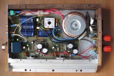
In my case I have two LM3886 on a single heat sink of 460 square centimeters (without the aluminum top).
Temp went from 29C (room temp) to 38C running idle. With jazz and classical music at normal level it went from 312C (room temp) to 43C. This was the hottest I've measured.
See Rod Elliott's article on Ground Loop Breakers. Earthing (Grounding) Your Hi-Fi - Tricks and Techniques
National does advise 100nF ceramic and 10uF electrolytic as close to the power pins of the LM3886 as possible.
National does advise 100nF ceramic and 10uF electrolytic as close to the power pins of the LM3886 as possible.
- Status
- This old topic is closed. If you want to reopen this topic, contact a moderator using the "Report Post" button.
- Home
- Amplifiers
- Chip Amps
- LM3886 optimisation and power supply review