Hello all,
I just completed my first gainclone. I gutted the main amplifiers on a old realistic stereo and implemented 2 LM3875s. I have a problem where when I turn the stereo off, it makes a POP and the speaker cone moves A LOT.
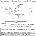
I'm running it a 55 volts, using this schematic
but instead of 5600uf caps on the + and -, I'm using 10000uf caps...
Why is the amplifier doing this? What can I do to fix the problem?
Thanks
I just completed my first gainclone. I gutted the main amplifiers on a old realistic stereo and implemented 2 LM3875s. I have a problem where when I turn the stereo off, it makes a POP and the speaker cone moves A LOT.
I'm running it a 55 volts, using this schematic
but instead of 5600uf caps on the + and -, I'm using 10000uf caps...
Why is the amplifier doing this? What can I do to fix the problem?
Thanks
What schematic?
Mike
Here it is, sorry...
Attachments
See Data Sheet, Figure 2
The schematic you have is too simplified! Unfortunately, National encourages this by a not so well written data sheet...but if you're going to have something stable, it must be a lot closer to Figure 2...Output LR network, Zobel network, compensating caps on the feedback to shape the loopgain, small bypass caps across the rails as well as the big ones...
Your design is marginally stable, so just the noise from the interruption of the AC supply at turn off is amplified horrendously, overdriving the amp, and making a huge pop at the output.
There was a similar thread about a similar problem a while ago, but I haven't tried to search for it.
There is no ground reference path on the '+' input of the amp AND the gain is 30 dB down to DC. National says the capacitor is optional but it's very good to include it. There is no harm increasing the value over the 22uF shown. It just moves the low end -3dB frequency lower.
G²
G²

55 volts is too much
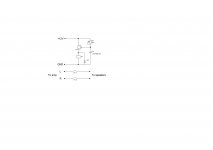
55 volts is too much, you need 25-27 volts on each arm. In LM3875 no mute function, and you need delay of loudspeakers connection, something like this. Or you can use upc1237 if you want speakers protection and delay.Hello all,
I just completed my first gainclone. I gutted the main amplifiers on a old realistic stereo and implemented 2 LM3875s. I have a problem where when I turn the stereo off, it makes a POP and the speaker cone moves A LOT.
I'm running it a 55 volts, using this schematic
but instead of 5600uf caps on the + and -, I'm using 10000uf caps...
Why is the amplifier doing this? What can I do to fix the problem?
Thanks
Attachments
55Vdc is just perfect for a 3875.
It can be single polarity supply 0Vdc to +55Vdc, or 0Vdc to -55Vdc, or dual polarity supply, +27.5Vdc, 0Vdc -27.5Vdc, or dual polarity with the centre voltage not at 0Vdc, eg. +35Vdc, 7.5Vdc, 20Vdc. It can even have the centre voltage not at the arithmetic mean between the two supply polarities.
It can be single polarity supply 0Vdc to +55Vdc, or 0Vdc to -55Vdc, or dual polarity supply, +27.5Vdc, 0Vdc -27.5Vdc, or dual polarity with the centre voltage not at 0Vdc, eg. +35Vdc, 7.5Vdc, 20Vdc. It can even have the centre voltage not at the arithmetic mean between the two supply polarities.
He hasn't specified what power supply he uses. Maybe it +55v and -55v, how i can understand that the 55volts it is the sum of voltages?55Vdc is just perfect for a 3875.
It can be single polarity supply 0Vdc to +55Vdc, or 0Vdc to -55Vdc, or dual polarity supply, +27.5Vdc, 0Vdc -27.5Vdc, or dual polarity with the centre voltage not at 0Vdc, eg. +35Vdc, 7.5Vdc, 20Vdc. It can even have the centre voltage not at the arithmetic mean between the two supply polarities.
Thank ya'll very much for the input.
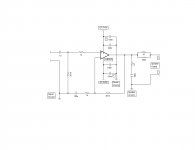
I'm looking at the schematic that was posted and I think that I'm going to use it.
Speaker protection is a little beyond me at this point.
Here is my power supply, coming from a center tapped transfo.
From bridge rectifier.
55v+ 0 55v-
| | |
| | |
-----||------------||----
| | |
55v+ GND 55v-
Caps are 10000uf 80v.
Using this power supply and said voltage, would the supplied schematic be OK?
Attachments
As i say, +-55 volts is too much for LM3875, using such big voltage this is strongly risk for your acoustic systems. You need +-27 voltsThank ya'll very much for the input.
I'm looking at the schematic that was posted and I think that I'm going to use it.
Speaker protection is a little beyond me at this point.
Here is my power supply, coming from a center tapped transfo.
From bridge rectifier.
55v+ 0 55v-
| | |
| | |
-----||------------||----
| | |
55v+ GND 55v-
Caps are 10000uf 80v.
Using this power supply and said voltage, would the supplied schematic be OK?
Last edited:
5.6m = 5600uF. Bigger is better so keep your 10000u ones. The 100nF caps must be placed as close to the IC as possible. Anyway, the one most likely source of your pop is the lack of a coupling capacitor in the feedback loop.
As for one channel being louder, your gain setting resistors probably have high tolerances, or you got the resistors wrong on one of the channels. Buy 10-20 resistors of the values you need for gain setting. You'll quickly find use for them in other projects anyway. Using your multimeter select the ones that are closest to each other from the batch, and use those for the feedback network of the amplifier (the resistor from output to inverting input, and the one from inverting input to ground).
And yes +/-55v is way too much. +/-40 at most. In fact, you're lucky they didn't blow up yet... and the protection on those chipamps sounds UGLY.
Last edited:
...but very helpful if you dont read datasheets =)... and the protection on those chipamps sounds UGLY.
Not trying to sound ignorant, but the datasheet said that it could take up to 84volts.
I figured that 55v was WAY below to MAX.
Also, would this inductor work?
http://www.mouser.com/ProductDetail...=sGAEpiMZZMv126LJFLh8y/i5aze5xuXYCP8ejQYbxjo=
I beginning to think that I'm in over my head. The reason why I chose the LM3875 was because I thought that it could handle the voltage that was available within the amplifier.
As for using the 55v, the amplifier sounds fine. It doesn't seem like it's too much voltage for it.
Last edited by a moderator:
84v total, measured from positive rail to negative rail, not from one of the rails to ground. +/-55v is 110v.
55 volts measured from positive rail to negative rail, not positive to ground.
55 volts measured from positive rail to negative rail, not positive to ground.
Then your earlier diagram was misleading. There is no problem in that case, so let's get on and tackle the pop. Insert a 22uF 50v cap in the feedback loop, lift the end of the 680 ohms resistor that goes to ground and insert the cap between it and ground.
- Status
- This old topic is closed. If you want to reopen this topic, contact a moderator using the "Report Post" button.
- Home
- Amplifiers
- Chip Amps
- LM3886 loud pop when turned off