Care to share a link? 100mV++ look impossible to me, unless the chip were configured with a DC gain greater than unity.This is not a "non-issue".
Look at some of the reports of Peter's DC coupled amplifiers and you see output offsets wandering all over the place with changes in volume. The worst cases come out exceeding 100mVdc of output offset.
Perhaps this one will be more lucky?
It probably sounds less forwards, less hard than chipamp.com.
It probably sounds better than the LM3886 datasheet example.
It will not sound better than the Decibel Dungeon Inverting amplifiers.
It will not sound better, nor as good as the MyRef series.
It probably sounds less forwards, less hard than chipamp.com.
It probably sounds better than the LM3886 datasheet example.
It will not sound better than the Decibel Dungeon Inverting amplifiers.
It will not sound better, nor as good as the MyRef series.
Attachments
Last edited:
how you call first condenser from input after the pot.. and why when i put it in my amp , amp works for 3 sec and then output goes to rail. sorry for offtopic but this looks like closest place to ask
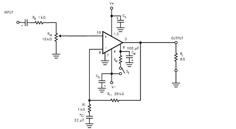
If you've got a normal LM3886 kit that resembles the datasheet application. . . just put a 12k resistor from pin10 (+input) to pin7 (ground) and then the offset will probably stay at less than 0.1v. Put the new resistor directly onto the chip pins. Now you can install your input coupling cap.
Last edited:
it is datasheet scheme .. v- is on output when there is condenser ,i put it after pot before 1k , when there is in+ in air (not connected) then on output is v+ , and everything ok when just pot connected but 20mv offset , is this normal... i try that 12k from 7 to 10pin ...thanks on answer
Attachments
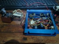
Metal tab version? You need the thermal pad and shoulder washer for electrical insulation safety.
And the shell of that metal enclosure needs grounded well.
it is maid for car use where it sits in plastic shell what diretcs cold air trough it and i find that better cooling capabilities without mica insulator... i just plug it to smal trafo from mains for testing...inverter in car has protections if something goes wrong but there is no way something could go wrong the way it sits in trhat plastic shell.... i have tested with 0,1uf and 4,7uf input capacitor and maybe i am deaf but there is no difference in sound

Well, 12k would have brought the offset down below 80mv in most cases. And, in the case of 12k input loading resistor, we could have experimented making the feedback divider 15k vs 470R--I wonder if anyone has tried that?
However, your 6k8 is fine--it won't hurt the amplifier although there could be a slight tone difference from a heavier input load like that. If you didn't notice or object to the tone difference, then keep using that 6k8 and enjoy the very low offset. Kudos for fixing it!
However, your 6k8 is fine--it won't hurt the amplifier although there could be a slight tone difference from a heavier input load like that. If you didn't notice or object to the tone difference, then keep using that 6k8 and enjoy the very low offset. Kudos for fixing it!
Well, 12k would have brought the offset down below 80mv in most cases. And, in the case of 12k input loading resistor, we could have experimented making the feedback divider 15k vs 470R--I wonder if anyone has tried that? ....
,i have one lm3875 in proggres waiting for some parts.... i can try that on it altough i dont fully understand what would happen and not yet translated what exact scheme is using 2 sided pcb from ebay cant trace traces well.
However, your 6k8 is fine--it won't hurt the amplifier although there could be a slight tone difference from a heavier input load like that. If you didn't notice or object to the tone difference, then keep using that 6k8 and enjoy the very low offset. Kudos for fixing it!
thanks for big help!!! ... and fast also...
This can be patched by using a 20k pot in parallel with a 27k resistor load. The new 27k resistor can be attached from in+ to ground pins of the chip. Adding the 27k will catch some of the pot wiper errata to prevent random speaker damage. . . which would otherwise be happening with the following schematic, as soon as the potentiometer begins to wear.A very quick edit to show what I did (except Rb is 220r):
I don't like that schematic.
That schematic is quite badly incomplete--Instead of that unstable tirade sounding abridgement, far more practical things to do with LM3886 would be the Decibel Dungeon inverting designs and of course, the MyRef.
For example, follow this link for good sounding simple gainclones: The Decibel Dungeon Gainclone index page with links to all chip amp articles.
P.S. please ignore the attached schematic below
Attachments
![q2ZJynV[1].png](/community/data/attachments/341/341123-01361e95d5168c15874493038b6c4345.jpg)
Last edited:
Perhaps this one will be more lucky?
It probably sounds less forwards, less hard than chipamp.com.
It probably sounds better than the LM3886 datasheet example.
It will not sound better than the Decibel Dungeon Inverting amplifiers.
It will not sound better, nor as good as the MyRef series.
Daniel, I'm afraid I don't like the input to this circuit. The hf rolloff varies with pot position, being 0 to 50k with 220pF, which is a big range and is at its highest frequency with maximum volume and effectively not doing anything.
Secondly the 220pF comes after the 2.2uF capacitor which I presume is a foil cap and will have noticeable inductance at 20k and that's not an interaction you want (though you could make it work for you if you were very careful and had a consistent and matching input impedance). Better to put a fixed RC before the pot that acts somewhere around 100kHz. See Linkwitz Labs for his 3886 hf rolloff.
with the amount of problems you people find everywhere one can easily think that it is actually impossible to make a chipamp.
As there is no best way, everyone tells the way he made a good one. There are not necessary things, but how can someone decide if he needs it if he doesn't know what are the possible consequences? You can most of the time just trust others in schematics, but how to tell if the one giving the advice actually knows what he made. And actually knows why.
")
Daniel, I'm afraid I don't like the input to this circuit. The hf rolloff varies with pot position, being 0 to 50k with 220pF, which is a big range and is at its highest frequency with maximum volume and effectively not doing anything.
Secondly the 220pF comes after the 2.2uF capacitor which I presume is a foil cap and will have noticeable inductance at 20k and that's not an interaction you want (though you could make it work for you if you were very careful and had a consistent and matching input impedance). Better to put a fixed RC before the pot that acts somewhere around 100kHz. See Linkwitz Labs for his 3886 hf rolloff.
Most foil caps have no appreciable inductance. The leads are NOT typically connected to the ends of the foil rolls. They usually connect to one entire edge of each roll. Just don't use them, otherwise.
Actually they do have noticeable inductance. If you measure their impedance it shades by 3 to 5 degrees around 20k. That's for a good PP cap from Wima (who must be somewhere near the top in knowing how to construct these things). It makes an interesting contrast with electrolytics where you see only various degrees of ESR, so you don't get the full 90 degree phase shift, ever, but you don't see it tailing off at the top. It's quite hard to know what the actual inductance is, because that shift in impedance is set against whatever the ESR is, which can be very low. And though I will have worked it out at some point I'm afraid I don't have a figure for it at the moment. Nonetheless, I still feel it would be better practice to have an RC first and then your coupling cap, thus avoiding any possible interaction.
- Status
- This old topic is closed. If you want to reopen this topic, contact a moderator using the "Report Post" button.
- Home
- Amplifiers
- Chip Amps
- LM3886 Input Resistor Position