Driver command issue
Really? LM1875's running on a 50v (25+25vAC) toroid putting out 36+36vdc? Well, yes, you'd want to maximize your heatsinks.")
I'm very, very jealous of this, so I'm going to go try it.
FYI: That voltage means 1 of 8 ohm loudspeaker per amplifier is the limit--which is normal usage anyway. Do check your crossovers carefully to make sure that there's not too much "against" the audio path.
Since LM1875 does transient peaks at 12 ampers, with average limited to 4 ampers. . .and both are with 36vdc rails. . . the mind boggles. . . One techno beat should x-max most drivers.
Its not going to put out incredible power average; however, you just described the one problem it shouldn't have, because its crude limiter won't stop that bass beat.
Its possible that you're running into that 4 amp limiter because of some inefficiency in the circuit; and once activated, dynamics (transients) are also limited.
Consider that there's two budgets:
Average SPL with 4 ampers
Dynamics with 12 ampers
And, if you spend the small one, then you can't use the big one.
Can you post a circuit diagram and some photos?
P.S. Considering the type of music, perhaps you would enjoy an Aphex aural enhancer (a studio/nightclub standard) to remove some of the compression from recorded materials. It may be more like what you're expecting to hear.
eketehe said:. . . my previous Lm1875 was operate at 24.2VDC from 50VAC toroid, with 4 x 4700uf in paralel per rail, is that suficient? the network is as per datasheet schematic.
yes the chips is as hot as irons, i also put an extra heatsink.
I will try to find that high speed 12'
i'm already stisfied with the real sounds in mid and high, especially for vocal, strings and mid-high percussion. i just need more detail for kick bass to meet low freq bass from subwoofer.
the detail i mean, is just like what the lm3886 produced. the good ambience is come when its meet the low sound from subwoofer. i'm using the crossover active to awake the 20hz-100hz freq.
my idea is to combine thats all good sound. thought the 3886 is more flexible, its handle madonna's techno very good.
Really? LM1875's running on a 50v (25+25vAC) toroid putting out 36+36vdc? Well, yes, you'd want to maximize your heatsinks.
I'm very, very jealous of this, so I'm going to go try it.
FYI: That voltage means 1 of 8 ohm loudspeaker per amplifier is the limit--which is normal usage anyway. Do check your crossovers carefully to make sure that there's not too much "against" the audio path.
Since LM1875 does transient peaks at 12 ampers, with average limited to 4 ampers. . .and both are with 36vdc rails. . . the mind boggles. . . One techno beat should x-max most drivers.
Its not going to put out incredible power average; however, you just described the one problem it shouldn't have, because its crude limiter won't stop that bass beat.
Its possible that you're running into that 4 amp limiter because of some inefficiency in the circuit; and once activated, dynamics (transients) are also limited.
Consider that there's two budgets:
Average SPL with 4 ampers
Dynamics with 12 ampers
And, if you spend the small one, then you can't use the big one.
Can you post a circuit diagram and some photos?
P.S. Considering the type of music, perhaps you would enjoy an Aphex aural enhancer (a studio/nightclub standard) to remove some of the compression from recorded materials. It may be more like what you're expecting to hear.
Re: Driver command issue
danielwritesbac said:
Really? LM1875's running on a 50v (25+25vAC) toroid putting out 36+36vdc? Well, yes, you'd want to maximize your heatsinks.
I'm very, very jealous of this, so I'm going to go try it.
=============
No Daniel, don't do that!
sorry for put some wrong info, its 18vac to out 24+24vdc, from single 50VA, i think its 5 Ampere. for dual mono.
i have try this lm1875 with 24vac to out 33+33vdc, it was very hot, even run in low db for test,i change it,n use the transformator for the bigger lm 3886 for its just sounds normal.. not excelent or even better. if 4 ampere is the minimum, so i sud purchase the bigger trafo, maybe 100VA. i've been considering this,but do you think the more ampere will strengthten the bass? how much Ampere is the best for sound repro correctly? i check that good 170VA toroid will costs almost 50 times of the chip price.
i'm an omni, from mainstream jazz, led zepelin to the powerfull technos,world n local n play 'em all depend on moods.
the speakers as yor suggestion maybe will hard to find here, but i writes 'em in note for hunting. i can not purchase the ready made
high end for its costs my house haha.sorry for that much price comparison.
i'm plans to separate all speakers, each in single box. i know thts will be less dynamic in low db but will put track's instruments in the correct place n harmonic in more db.
i'm still tests some paralel and serial passive cross over in trial. can not gives you any diagram this time. i have problem to understand inductors, lh n mh you know 'em stands for? aren't they are size for long, or weight or maybe spins of inductor?
you know i'm a begginer, everything are new for me. i do this soldering action,many kind of chipamp for trial to change my old car's audio. yes i have try this small LM using an inverter. its the good energy waster the battery was droping.
Re: Re: Driver command issue
Your 18+18vAC transformer should do a very nice job. For an LM1875 stereo pair, 72va is a recommended minimum.
Amperage, as in volt-amps. . . Let's have a look at a common 36v, 1 amp center tap transfo. That's also 36va. Two ampers would be 72va. Three ampers would be 108va. Volts times amps.
VA requirement can be decreased by extra capacitance at the power supply. For instance, a 72va can successfully run an LM1875 stereo pair, if given 4700uF per rail. One would suggest to add a bit of headroom (transformer quality control varies), so perhaps 100va for an LM1875 stereo pair.
Maybe the 50 va that you already own can do a nice job with 10,000uF per rail? I don't know what Cascada would say about that, but its worth a try.
Inductors can be measured with a meter. Just swing it over to "mh" on the dial. Let's compare a few:
20 gauge economy air core inductor--good for all 4 ohm speakers and always good at 1mh or less. Also good for blocking bass from midrange and tweeter (2nd order crossover).
22 gauge super-cheap air core inductor--good for super-small values. Also good for blocking bass from tweeter (2nd order crossover).
18 gauge air core inductor--good for passing a strong audio signal. Also very good for efficient BSC circuits and notch filters.
Iron core inductor--good for the woofer in a 3-way system, if using 2nd order and higher crossovers. Not for use in 1st order crossovers, because there's usually a screech that needs to be thoroughly blocked by a cap.
Expense on inductors can be controlled by using 4 ohm drivers because that's half-size inductors; however, you'll need to run the amplifier at slightly less voltage OR add a double-size heatsink.
Expense on capacitors can be controlled by using either 100v+ (not 50v) electrolytics or the better polyester caps, like Wima (this is also true of amplifier signal parts). Avoid electrolytics smaller than 2.5uF because they won't match frequency response of modeling software or examples.
After building, you may wish to upgrade some of the HF pass caps (carries signal to midrange and tweeter) to polypro cap types. However, the electrolytics can help you decrease development costs (cheaper to experiement with).
The application difference between LM3886 and LM1875 is that the average SPL of the larger chip can be greater. However, on transients, there may be only 3 to 5 db difference. So, just run the LM1875's on efficient speakers.
Amplifier diagram? The reason that I asked for one is the driver command issue. If you're getting different results between those two chips. . . it isn't in the chip, so check the circuit board. Between the two amplifier chips, the most likely possibility to cause LM1875 inferior driver command, would be if its input filter cap is either absent or a too-large capacitance value.
eketehe said:
sorry for put some wrong info, its 18vac to out 24+24vdc, from single 50VA, i think its 5 Ampere. for dual mono.
i have try this lm1875 with 24vac to out 33+33vdc, it was very hot, even run in low db for test,i change it,n use the transformator for the bigger lm 3886 for its just sounds normal.. not excelent or even better. if 4 ampere is the minimum, so i sud purchase the bigger trafo, maybe 100VA. i've been considering this,but do you think the more ampere will strengthten the bass? how much Ampere is the best for sound repro correctly? i check that good 170VA toroid will costs almost 50 times of the chip price.
i'm an omni, from mainstream jazz, led zepelin to the powerfull technos,world n local n play 'em all depend on moods.
the speakers as yor suggestion maybe will hard to find here, but i writes 'em in note for hunting. i can not purchase the ready made
high end for its costs my house haha.sorry for that much price comparison.
i'm plans to separate all speakers, each in single box. i know thts will be less dynamic in low db but will put track's instruments in the correct place n harmonic in more db.
i'm still tests some paralel and serial passive cross over in trial. can not gives you any diagram this time. i have problem to understand inductors, lh n mh you know 'em stands for? aren't they are size for long, or weight or maybe spins of inductor?
you know i'm a begginer, everything are new for me. i do this soldering action,many kind of chipamp for trial to change my old car's audio. yes i have try this small LM using an inverter. its the good energy waster the battery was droping.
Your 18+18vAC transformer should do a very nice job. For an LM1875 stereo pair, 72va is a recommended minimum.
Amperage, as in volt-amps. . . Let's have a look at a common 36v, 1 amp center tap transfo. That's also 36va. Two ampers would be 72va. Three ampers would be 108va. Volts times amps.
VA requirement can be decreased by extra capacitance at the power supply. For instance, a 72va can successfully run an LM1875 stereo pair, if given 4700uF per rail. One would suggest to add a bit of headroom (transformer quality control varies), so perhaps 100va for an LM1875 stereo pair.
Maybe the 50 va that you already own can do a nice job with 10,000uF per rail? I don't know what Cascada would say about that, but its worth a try.
Inductors can be measured with a meter. Just swing it over to "mh" on the dial. Let's compare a few:
20 gauge economy air core inductor--good for all 4 ohm speakers and always good at 1mh or less. Also good for blocking bass from midrange and tweeter (2nd order crossover).
22 gauge super-cheap air core inductor--good for super-small values. Also good for blocking bass from tweeter (2nd order crossover).
18 gauge air core inductor--good for passing a strong audio signal. Also very good for efficient BSC circuits and notch filters.
Iron core inductor--good for the woofer in a 3-way system, if using 2nd order and higher crossovers. Not for use in 1st order crossovers, because there's usually a screech that needs to be thoroughly blocked by a cap.
Expense on inductors can be controlled by using 4 ohm drivers because that's half-size inductors; however, you'll need to run the amplifier at slightly less voltage OR add a double-size heatsink.
Expense on capacitors can be controlled by using either 100v+ (not 50v) electrolytics or the better polyester caps, like Wima (this is also true of amplifier signal parts). Avoid electrolytics smaller than 2.5uF because they won't match frequency response of modeling software or examples.
After building, you may wish to upgrade some of the HF pass caps (carries signal to midrange and tweeter) to polypro cap types. However, the electrolytics can help you decrease development costs (cheaper to experiement with).
The application difference between LM3886 and LM1875 is that the average SPL of the larger chip can be greater. However, on transients, there may be only 3 to 5 db difference. So, just run the LM1875's on efficient speakers.
Amplifier diagram? The reason that I asked for one is the driver command issue. If you're getting different results between those two chips. . . it isn't in the chip, so check the circuit board. Between the two amplifier chips, the most likely possibility to cause LM1875 inferior driver command, would be if its input filter cap is either absent or a too-large capacitance value.
Re: Re: Re: Driver command issue
Tks daniel,
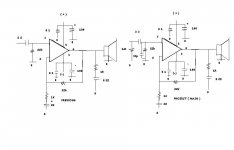
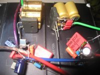
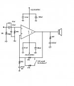
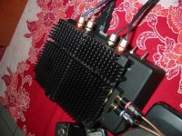
here belows is the diagram, sorry for bad picture, the mouse keep movin on.
the 1st pic is my previous ( PCB ). the 2nd pic is my project without PCB,learn from you i insert the 330pf.
i re-made 2 mono, looks not similar but the sounds similar n runs some test.
i think the power suply the main problem for the previous amp, the toroid only produce less than 1 amp per channel just accord your info. i tests my project dual amp with 2 usual trafos,reads 5A and 3A, all 18-0-18VAC. and 4 x 4700/35V and 4 x 2200/25v, change 'em viceviersa. their sounds just great to play my 2 way speakers ( 3' tweeter + 4' midwoofer ), then to my 3ways kitchen speakers. they're also sings great, both laura figy's or madonna's. and also the bass detail i want just sounds up. i did the happy laugh for that haha i did it.
here are some result :
there almost no different beetween amps w/ the bigger and smaller trafo to play on the 2 way up to speakers limit. loud enough. then to 3 ways kitchen, then i find that the bigger produces... what sud i say.. maybe bolder sound. especialy in louder volume.the small powered amp also loose the bass detail. i have no equipment to explain this experience detaily,but this chipamp is special, there is no humm or hissing for almost peak when turns the 50K type B pot for about 3/4 to end. yes there was wind like sound for rest.. whatever, i never play that loud.
i forgot to check the current of both trafos in ac or dc. my friend told me that the local trafo product cheat us to state more ampere then the actual. also the toroids. i check there was +/-24.2VDC coming from the 5A, and only 22.4VDC coming from the smaller.
I just miss one thing... the heat! i just didn't find the usual heat in my test, just little warm, i don't know if the produser hv rvsd their amp, or my heatsink just OK,i better do the heatsink more carefull, i'm affraid if the isolator fail,not delivers the heat properly.
LM3886 might be able to going louder but this smaller LM is just my type. i will not play both amp for full throtle anyway haha.
I'm impressed with the dynamic and details when test my 2way speaker,few number parts of simple Lm1875, so that i made other dual mono, to drive the 2way speaker. i plans to make the portable amp to play songs from my handphone or mp3 player , i only change the filter caps with smaller 2.2 to hve more compact design.and 1ohm of speaker zobel R with 2.2ohm in paralel.
i leave my main project to finish this late project first, my thought, i will be in long journey of crossover and speakers tests so i need this to accompany me, and also i need more experience to make 'the best one .my alibi.
i'm about to finish this satelite project, but maybe you know the better small chipamps for recomendations?
i have record your guidance for driver, and crossover network.
maybe i will drowned a while onto some tests. i will invite you to check development. if you don't mind. maybe in new topic for this lessons also has going far far away from original topic.
well then, thankyou verymuch.
danielwritesbac said:
The application difference between LM3886 and LM1875 is that the average SPL of the larger chip can be greater. However, on transients, there may be only 3 to 5 db difference. So, just run the LM1875's on efficient speakers.
Amplifier diagram? The reason that I asked for one is the driver command issue. If you're getting different results between those two chips. . . it isn't in the chip, so check the circuit board. Between the two amplifier chips, the most likely possibility to cause LM1875 inferior driver command, would be if its input filter cap is either absent or a too-large capacitance value.
Tks daniel,
here belows is the diagram, sorry for bad picture, the mouse keep movin on.
the 1st pic is my previous ( PCB ). the 2nd pic is my project without PCB,learn from you i insert the 330pf.
i re-made 2 mono, looks not similar but the sounds similar
n runs some test. i think the power suply the main problem for the previous amp, the toroid only produce less than 1 amp per channel just accord your info. i tests my project dual amp with 2 usual trafos,reads 5A and 3A, all 18-0-18VAC. and 4 x 4700/35V and 4 x 2200/25v, change 'em viceviersa. their sounds just great to play my 2 way speakers ( 3' tweeter + 4' midwoofer ), then to my 3ways kitchen speakers. they're also sings great, both laura figy's or madonna's. and also the bass detail i want just sounds up. i did the happy laugh for that haha i did it.
here are some result :
there almost no different beetween amps w/ the bigger and smaller trafo to play on the 2 way up to speakers limit. loud enough. then to 3 ways kitchen, then i find that the bigger produces... what sud i say.. maybe bolder sound. especialy in louder volume.the small powered amp also loose the bass detail. i have no equipment to explain this experience detaily,but this chipamp is special, there is no humm or hissing for almost peak when turns the 50K type B pot for about 3/4 to end. yes there was wind like sound for rest.. whatever, i never play that loud.
i forgot to check the current of both trafos in ac or dc. my friend told me that the local trafo product cheat us to state more ampere then the actual. also the toroids. i check there was +/-24.2VDC coming from the 5A, and only 22.4VDC coming from the smaller.
I just miss one thing... the heat! i just didn't find the usual heat in my test, just little warm, i don't know if the produser hv rvsd their amp, or my heatsink just OK,i better do the heatsink more carefull, i'm affraid if the isolator fail,not delivers the heat properly.
LM3886 might be able to going louder but this smaller LM is just my type. i will not play both amp for full throtle anyway haha.
I'm impressed with the dynamic and details when test my 2way speaker,few number parts of simple Lm1875, so that i made other dual mono, to drive the 2way speaker. i plans to make the portable amp to play songs from my handphone or mp3 player , i only change the filter caps with smaller 2.2 to hve more compact design.and 1ohm of speaker zobel R with 2.2ohm in paralel.
i leave my main project to finish this late project first, my thought, i will be in long journey of crossover and speakers tests so i need this to accompany me, and also i need more experience to make 'the best one .my alibi
. i'm about to finish this satelite project, but maybe you know the better small chipamps for recomendations?
i have record your guidance for driver, and crossover network.
maybe i will drowned a while onto some tests. i will invite you to check development. if you don't mind. maybe in new topic for this lessons also has going far far away from original topic.
well then, thankyou verymuch.
Attachments
The amplifiers look great!
On your speaker output zobel: The amplifier isn't rated for a 1 ohm load. So, I'd change that resistor up to at least 2.2 ohms. Four ohms is also an option, although a brighter sound.
On the final steps, there's some fine tuning options, although they are unnecessary. Just a couple of things for fine tune (personal tastes):
On your gain setting: Well, if you're happy with the loudness, its just fine. However in the NFB (gain loop structure), there are options to use 33k or 44k instead of the 22k. In case the source is an Ipod, television, headphone source of some kind, then you might want to review the gain options. The sonic consequences of higher gain are problematic, so I'll also give some fine tuning options.
On the local decoupling caps: The amplifier changes sound depending on the size of cap. Currently, the 100uF are just fine. However, you do have options of 100, 220, 330, 440, 680, and 1000. Larger numbers make less upper midrange, and potentially more bass. Consider it a fine tuning option.
On the voltage: Well, if the higher voltage doesn't get the amp hot, then its nice to have the extra dynamic power.
On CI, the protection cap on the NFB (gain loop structure): Its possible to add either 0.1uF or 0.047uF ceramic capacitor in addition to the big capacitor if you'd like a brighter, airy, sound. The smaller values will only increase the very highest of pitches--something good to do if you have too much midrange.
All told, the amplifiers look good, and there's no changes necessary except for just one thing.
That one thing is the speaker output zobel's resistor. If using 1 ohm, then it needs to be a 1 watt resistor. Otherwise a 2.2 ohm 1/2 watt can do just fine. Or, a 1/4w 4 ohm resistor can do fine too. Here's a clue. The really cheap 100v polyester cap (0.22uF) uses the 2.2 ohm resistor; however, a better cap uses the 4 ohm resistor for speaker output zobel.
Great job on the diagrams!!
Dear Daniel,
Tks again,
I'm looking for more sound experience ,before i have put 220 for decoupling, but i change with 100 for slimer size. but i will retry it and try your other suggest,for i want to know the diferent.
i don't recognize the caps well, maybe you can tell me which is the ceramic's? or : MKS,MKP,MKC,FKP, MKT, MTP or maybe you can adv me what are they best for? the same question for Resistors, which are best for amp, or pre-amp : vitrum, metal film, carbon , or beslag ( or bes... something )... so that i able to fit some correct item for good audiosystem, i only know that the cheap electrolit caps blowing under the voltage limit and also blows all my amp haha
Tks again,
I'm looking for more sound experience ,before i have put 220 for decoupling, but i change with 100 for slimer size. but i will retry it and try your other suggest,for i want to know the diferent.
i don't recognize the caps well, maybe you can tell me which is the ceramic's? or : MKS,MKP,MKC,FKP, MKT, MTP or maybe you can adv me what are they best for? the same question for Resistors, which are best for amp, or pre-amp : vitrum, metal film, carbon , or beslag ( or bes... something )... so that i able to fit some correct item for good audiosystem,
i only know that the cheap electrolit caps blowing under the voltage limit and also blows all my amp hahaCeramic caps are typically used as bypass caps and many other uses too. They're the tan/orange and cheap little disc shaped things. A 0.1uF is marked either 100nF or code 104. And, a 0.047uF is marked either 47nF or code 473. Ceramic is fantastic for audio and radio use because of generally very good quality results.
They can also protect your amp in case of electrolytic cap failure--with ceramic bypasses, the amp will probably keep right on playing.
Tip: When soldering these, hold the cap with your fingers because they can't take more heat than you can. Flux is also mighty helpful in keeping these cool while soldering--soldering very fast.
On the resistor type, I honestly have no idea whatsoever. Its probable that most resistors are just fine. However, the length of the leads matters greatly--needs to be short.
my satelite project just done
Hi Daniel,
tks for the clues, realy brainstorming.
i'm back from several tests.
the C1:
when i'm put the additional 47n, firstly i don't feel any diference. then i change the main 2.2mf with this 47n, and try other caps 82n,100n,220n,etc to 3.3mf. then i know the different. so i set the c1 back to 2,2mf + additional 47n as my favourite. they're about the bandwidht aren't they?. i found the smaller value caps will cut/hide the low tone.
the NFB network resistor.
i only try 33K, 47K, and 2x47K in paralel to compare with the original 22K . as you said, they're about loudness setting. i think there other thing. when i use the 47K, the sounds more firmly. when i use the 22K the sounds is about half of 47K, but i feel the sound is going outer or wider, more dynamic on stereo, umh what sud i say... just like a little surround. ithink i need a little colouration for my 2way speakers will be something nice.anyway, i set the R to 2 x 47K in paralel, with switch on/off for more exploration.
the decoupling caps,
i also try pair of 220/470 n the big 1000mf. i feel there's no significant diferential, maybe i have tests em with the bigger trafo, i set back to original 100mf. there's extreme heat when i combined the 1000mf with 47K on NFB with +/- 31VDC.
The speaker Zobel.
I set it as per your suggestion, 4R7, honestly i don't feel any differential either. isn't it a speaker protector system?
i also think about the last kitchen's lm 3886. what if the speaker zobel is unsuficient n will brooke the speakers.
as you told me before, thats all about taste right?
here belows is my final diagram, with 22.4VDC and 31VDC selector. i like it runs on 31VDC for more living musics, but i also have to carefull with the extra heat. maybe you will adv some correction? i make it knock down, its able for correction.
i maybe consider the smaller C1 and 47K on NFB for my next project with the bigger speakers. but i think about the original datasheet diagram, do you think is it safe to set NFB at that loudness? The National set the original for some good reason, what do you think?
Hey i'd like to thank you verymuch for all your info, now my knowledge increasing from zero to zero point five haha i must be careful to say 'best sound'... they're so relative. this will be my turning point in DIYing something, try the fully mods before finish it
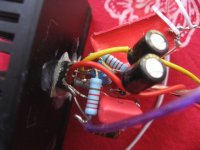
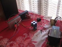
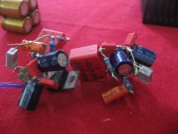
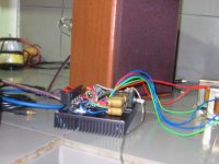
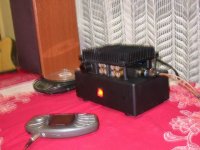
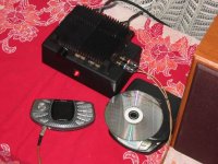
here some pictures, bad looking, i think to shows some elcon we'll be a face lift... blah not working. but its just 'as compact as' i want, and though enough
On your gain setting: Well, if you're happy with the loudness, its just fine. However in the NFB (gain loop structure), there are options to use 33k or 44k instead of the 22k. In case the source is an Ipod, television, headphone source of some kind, then you might want to review the gain options. The sonic consequences of higher gain are problematic, so I'll also give some fine tuning options.
Hi Daniel,
tks for the clues, realy brainstorming.
i'm back from several tests.
the C1:
when i'm put the additional 47n, firstly i don't feel any diference. then i change the main 2.2mf with this 47n, and try other caps 82n,100n,220n,etc to 3.3mf. then i know the different. so i set the c1 back to 2,2mf + additional 47n as my favourite. they're about the bandwidht aren't they?. i found the smaller value caps will cut/hide the low tone.
the NFB network resistor.
i only try 33K, 47K, and 2x47K in paralel to compare with the original 22K . as you said, they're about loudness setting. i think there other thing. when i use the 47K, the sounds more firmly. when i use the 22K the sounds is about half of 47K, but i feel the sound is going outer or wider, more dynamic on stereo, umh what sud i say... just like a little surround. ithink i need a little colouration for my 2way speakers will be something nice.anyway, i set the R to 2 x 47K in paralel, with switch on/off for more exploration.
the decoupling caps,
i also try pair of 220/470 n the big 1000mf. i feel there's no significant diferential, maybe i have tests em with the bigger trafo, i set back to original 100mf. there's extreme heat when i combined the 1000mf with 47K on NFB with +/- 31VDC.
The speaker Zobel.
I set it as per your suggestion, 4R7, honestly i don't feel any differential either. isn't it a speaker protector system?
i also think about the last kitchen's lm 3886. what if the speaker zobel is unsuficient n will brooke the speakers.
A Thiele network on the output in lieu of an output Zobel will include an inductor
as you told me before, thats all about taste right?
here belows is my final diagram, with 22.4VDC and 31VDC selector. i like it runs on 31VDC for more living musics, but i also have to carefull with the extra heat. maybe you will adv some correction? i make it knock down, its able for correction.
i maybe consider the smaller C1 and 47K on NFB for my next project with the bigger speakers. but i think about the original datasheet diagram, do you think is it safe to set NFB at that loudness? The National set the original for some good reason, what do you think?
Hey i'd like to thank you verymuch for all your info, now my knowledge increasing from zero to zero point five haha i must be careful to say 'best sound'... they're so relative. this will be my turning point in DIYing something, try the fully mods before finish it
here some pictures, bad looking, i think to shows some elcon we'll be a face lift... blah not working. but its just 'as compact as' i want, and though enough
Attachments
Re: my satelite project just done
High voltage hazard!
I see in the photos, an exposed heatsink, and I also see metallic audio connectors leading to ground. This means that the amplifier could kill a person or pet unless the chip is electronically isolated from the heatsink. The "TF" chips should be safe; however, the "T" chips need an isolater (micas, insulating washers) kit. So, see if you can measure voltage between the exposed audio grounds and the exposed heatsink. Um, not with your fingers--use voltmeter. We like you and we want you to stay healthy. Sorry about the lecture, but its kind of scary.
I'm glad you had some good times with the fine tuning.
For the NFB resistors, try choosing the value with the largest soundfield, or prettiest treble, and then adjusting its "partner" for the gain setting that you'd like.
Here's the "partner" values:
---nfb--------louder--------softer
For 22k nfb, 500R through 2k
For 33k nfb, 800R through 3k
For 47k nfb, 1.1k through 4k
For 50k nfb, 1.2k through 4.5k
For 56k nfb, 1.3k through 5k
For 100k nfb, 2.3k through 9k
For 120k nfb, 2.7k through 11k
For 150k nfb, 3.4k through 14k
*These are gain values of 45 through 12
Zobel
For the speaker output zobel, it stabilizes the amplifier. This is a good component, although I believe that one should avoid using it while fine tuning the amp (install zobel last), and also I believe that it shouldn't have a resistor value smaller than the maximum reference load of the amplifier (generally 3R).
So, it seems like your zobel is just fine because it doesn't have either of the usual errors in it.
eketehe said:
the NFB network resistor.
i only try 33K, 47K, and 2x47K in paralel to compare with the original 22K . as you said, they're about loudness setting. i think there other thing. when i use the 47K, the sounds more firmly. when i use the 22K the sounds is about half of 47K, but i feel the sound is going outer or wider, more dynamic on stereo, umh what sud i say... just like a little surround. ithink i need a little colouration for my 2way speakers will be something nice.anyway, i set the R to 2 x 47K in paralel, with switch on/off for more exploration.
The speaker Zobel.
I set it as per your suggestion, 4R7, honestly i don't feel any differential either. isn't it a speaker protector system?
i also think about the last kitchen's lm 3886. what if the speaker zobel is unsuficient n will brooke the speakers.
High voltage hazard!
I see in the photos, an exposed heatsink, and I also see metallic audio connectors leading to ground. This means that the amplifier could kill a person or pet unless the chip is electronically isolated from the heatsink. The "TF" chips should be safe; however, the "T" chips need an isolater (micas, insulating washers) kit. So, see if you can measure voltage between the exposed audio grounds and the exposed heatsink. Um, not with your fingers--use voltmeter. We like you and we want you to stay healthy. Sorry about the lecture, but its kind of scary.
I'm glad you had some good times with the fine tuning.
For the NFB resistors, try choosing the value with the largest soundfield, or prettiest treble, and then adjusting its "partner" for the gain setting that you'd like.
Here's the "partner" values:
---nfb--------louder--------softer
For 22k nfb, 500R through 2k
For 33k nfb, 800R through 3k
For 47k nfb, 1.1k through 4k
For 50k nfb, 1.2k through 4.5k
For 56k nfb, 1.3k through 5k
For 100k nfb, 2.3k through 9k
For 120k nfb, 2.7k through 11k
For 150k nfb, 3.4k through 14k
*These are gain values of 45 through 12
Zobel
For the speaker output zobel, it stabilizes the amplifier. This is a good component, although I believe that one should avoid using it while fine tuning the amp (install zobel last), and also I believe that it shouldn't have a resistor value smaller than the maximum reference load of the amplifier (generally 3R).
So, it seems like your zobel is just fine because it doesn't have either of the usual errors in it.
eketehe said:
i just realized that 1 chanel producing a smooth electrical noise, i thought its from coolcase near of left speakers. sound alike., but when i turn it off/on found yes, it was from my left drivers. so smooth, i find this problem two days after and i don't find this problem before, since test one by one of the three amp before instaling.
If you have eliminated external sources of noise, large MKPs (well, any foil cap) in the input signal path can pick up radiated PSU noise from inside the case through capacative coupling. I ran into this just recently myself
You can easily shield any such caps with some adhesive aluminum tape, and ground the tape shield to the chassis. Don't tie the shield to signal ground-- you'd just be putting the noise back into the signal path.
I see in the photos, an exposed heatsink, and I also see metallic audio connectors leading to ground. This means that the amplifier could kill a person or pet unless the chip is electronically isolated from the heatsink. The "TF" chips should be safe; however, the "T" chips need an isolater (micas, insulating washers) kit. So, see if you can measure voltage between the exposed audio grounds and the exposed heatsink. Um, not with your fingers--use voltmeter. We like you and we want you to stay healthy. Sorry about the lecture, but its kind of scary.
Whoa, seems i've made a big mistake.
the LM1875 isolated by mica and rubber paste, I tought tht was safe enough. i also always touch the heatsink for heat test.
well,Tks Daniel,
this also new for me, i need to check this.
can you kindly adv what is the TF and the T chips ?
You can easily shield any such caps with some adhesive aluminum tape, and ground the tape shield to the chassis. Don't tie the shield to signal ground-- you'd just be putting the noise back into the signal path.
Tks Bro,
i remember my friend was also teach me some thing like this to maximize of noise reduction, but a bit diferent. i was think its a bit scary : tie a cable at the input ground then turn on the pot to maximum ( without signal load ) and find the clearest by select place at body, and set the otherside of cable just there. it was also effective.
- Status
- This old topic is closed. If you want to reopen this topic, contact a moderator using the "Report Post" button.
- Home
- Amplifiers
- Chip Amps
- lm3886 electrical noise