http://www.diyaudio.com/forums/chip-amps/187527-point-point-lm3886.html
This is a good example of the necessary building methods.
Twist the supply and return together, this reduces the amount of transmitted hum.
Twist the input and its return or use a coax, this reduces the received hum.
All connections are firmly made by wrapping one wire around the other before applying solder. If you make your connections like this it will be a lot easier to add wires without it all coming apart.
Design the layout so that the circuit works as intended. If the schematic shows wires connecting to a single point, don't connect them in a chain. If the schematic doesn't show how to do the layout you will need to work it out for yourself. Look at the currents and how they may interact.
As far as which schematic to use, that is a difficult one. You need something with minimal parts that still will be stable.
Attachments
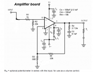
My edits to the schematic posted in Post #1:
R2 = 20 kΩ
R3 = 0 Ω
R6 = 0 Ω
C3 = 47 pF
C4 = DNP (Do Not Populate)
C10 = DNP
Add Cc = 180 pF from pin 9 to pin 10 (the two input pins) on the LM3886. This ensures stability near the supply rails.
Add Cz = 100 nF in series with Rz = 2.7 Ω, 2 W from pin 3 (OUT) of the LM3886 to GND. In series with the output connection (so from SPK to the speaker (+) terminal) add Lt = 2.0 uH (15 turns of AWG 18 / 1.0 mm diameter on an AA battery) in parallel with Rt = 1.5 Ω, 2 W. Rz, Cz form the Zobel network and Lt, Rt form the Thiele network. These networks are needed for stability, in particular with capacitive loads.
Keep SGND and GND as separate nodes and join them at one point only using R6 = 0 Ω (aka a piece of wire). This point should be at the speaker (-) output terminal for the best performance.
Keep the connections as short as you can.
Tom
How would the removal of some of the resistors and capacitors (r3, r6, c4, c10) affect the amplifier?
You mention implementing Cz and Rz, wouldn't that create a dummy load for when there are no speakers attached - and thus be optional?
I'm sure that twisting leads and keeping wire length down will reduce that faint, almost inaudible, hum which can be heard from a lot of amplifiers. However, at the moment there is a significant hum indicating that something has been connected incorrectly.
I would first like to rectify this unbearable noise, so that I can actually hear music over it, before I go about tidying up and making it completely silent.
I am new to the world of diy audio, likewise to my soldering iron haha, so I know I wouldn't be able to pull off any of the p2p examples that people have been giving ( at least not without shorting something out due to close proximity of all of the components). I also doubt that I'll be able to modify the circuit or rectify any issues that may arise if I've soldered everything on the IC like that.
From the datasheet:
LAYOUT, GROUND LOOPS AND STABILITY
The LM3886 is designed to be stable when operated at a
closed-loop gain of 10 or greater, but as with any other
high-current amplifier, the LM3886 can be made to oscillate
under certain conditions. These usually involve printed circuit
board layout or output/input coupling.
When designing a layout, it is important to return the load
ground, the output compensation ground, and the low level
(feedback and input) grounds to the circuit board common
ground point through separate paths. Otherwise, large currents
flowing along a ground conductor will generate voltages
on the conductor which can effectively act as signals at
the input, resulting in high frequency oscillation or excessive
distortion. It is advisable to keep the output compensation
components and the 0.1 μF supply decoupling capacitors as
close as possible to the LM3886 to reduce the effects of PCB
trace resistance and inductance. For the same reason, the
ground return paths should be as short as possible.
In general, with fast, high-current circuitry, all sorts of problems
can arise from improper grounding which again can be
avoided by returning all grounds separately to a common
point. Without isolating the ground signals and returning the
grounds to a common point, ground loops may occur.
These are problems caused by an incorrect grounding layout. You have sensitive inputs running across the transformer and between the power leads.
How would the removal of some of the resistors and capacitors (r3, r6, c4, c10) affect the amplifier?
The feedback network in the schematic you posted introduces a couple of poles in the 5-50 Hz range. I don't see any reason for this. It may be a rumble filter. Anyway. I don't think it's needed.
At the same time, the schematic did not include components that improve performance. Specifically, Cc = 180 pF, improves the performance as the amplifier approaches clipping. Without Cc, the LM3886 will oscillate as the output voltage approaches the positive supply rail. However, the addition of Cc introduces feed-forward and adds a bit of overshoot to the transient response. To compensate for this, C3 = 47 pF, R1 = 20 kΩ are added. This cleans up the transient response and you now have an amp that can generate a clean sine wave to the point of clipping without tendency to oscillate.
You mention implementing Cz and Rz, wouldn't that create a dummy load for when there are no speakers attached
That's the point. The LM3886 has an emitter follower output. Emitter followers do not work well in no-load conditions. In fact, they tend to oscillate under those conditions. The Zobel network loads the EF output stage and prevents oscillation.
I'm sure that twisting leads and keeping wire length down will reduce that faint, almost inaudible, hum which can be heard from a lot of amplifiers.
I agree.
However, at the moment there is a significant hum indicating that something has been connected incorrectly.
I bet you're listening to supply ripple feeding through the amp. Do you have access to an oscilloscope? Or an AC voltmeter? Try to measure the AC voltage on each supply rail. That might give some clues as to which one is (nearly) shorted to ground.
Tom
Unfortunately I don't have either :/
If you plan to continue to build electronic circuits, I strongly advise you to at least pick up a used Fluke 73 or something on eBay. Get one that's been tested or calibrated and is in good cosmetic shape. Even though I have much fancier meters available, the Fluke 73 I picked up in the early 1990ies still gets a fair amount of use.
There are other models as well. The 70-series and 80-series are workhorses. The newer 100-series is pretty nice as well.
You can get pretty far with a cheapie meter, but under some conditions the cheapie meters will actually give you wrong results, leading to confusion. Just spend the $50 on a used Fluke and you'll be set for life.
A Tektronix 2215 60 MHz scope will set you back about $150. Again, pay the bit more to get one that's tested. With the TEK2215 and Fluke 73, you'll have more measurement capabilities than many DIY folks.
Would any modification be required for the power supply circuit?
The power supply looks fine to me. I'd use a GBPC2510 for the diode bridge. The GBPC25xx-series can be bolted to the chassis and can handle 25 A. They're practically indestructible and easy to work with.
Tom
Last edited:
for most audio related DIY stuff i found that a soundcard and a pc is a decent tool.
there many many software available even for free, to use it as a 2 channel scope up to 20 ish khz. it may fall short sometimes when oscillatin is from a far higher fundamental, but for most stuff its just enough. a cheap dmm , and proper soldering tools are most of the time just enough.
there many many software available even for free, to use it as a 2 channel scope up to 20 ish khz. it may fall short sometimes when oscillatin is from a far higher fundamental, but for most stuff its just enough. a cheap dmm , and proper soldering tools are most of the time just enough.
Whilst I've always intended to get into building electronic circuits, this LM3886 build happened pretty spontaneously after my amplifier crapped out on me. Being a student atm, I don't quite have the cash to buy a new one and thought I'd give building one a go.
So I was pretty ill prepared.
I'll definitely check out one of the 70-series Fluke's for future builds.
Now, as far as the current build is going, I've done a whole tear down and re-build, keeping the wire lengths as short as possible. I have also implemented your suggested modifications tomchr.
Everything seems to be working just fine now. Thanks to all for the helpful comments! Especially those who didn't simply post more of the same examples of how to p2p solder...
There is a slight hum from one of the channels whilst the amp is on (Which I believe may be due to one of the IC's being too close to the transformer) and I get a 'pop' from the speakers whenever I turn the amp off, so I'll try to rectify that now.
Any suggestions as to how to remove the popping sound? Would I have to implement a mute switch to flip before turning off the amp or is there a better way?
I'm guessing the turn-off pop was due to Cmute (cap from the MUTE pin to GND) being missing in action.
A quiet hum is normal in a rat's nest build. You can reduce that by cleaning up the layout. You should be able to get below 1 mV of hum on the output. I routinely get below 10 uV in my PCB-based setups.
Tom
A quiet hum is normal in a rat's nest build. You can reduce that by cleaning up the layout. You should be able to get below 1 mV of hum on the output. I routinely get below 10 uV in my PCB-based setups.
Tom
I expect <<1mVac of Hum+Noise.You should be able to get below 1 mV of hum on the output
I regularly get a reading of 0.0mVac for H+N, indicating approximately <0.05mVac
Any reading above 0.3mVac is a failure in my book.
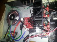
Hi, I also have a hum problem. I built this LM3886 gainclone with pcb board from chipamp.com. Only difference in amp part was i used 220ohm as R1, which maybe should be 1k. Also used 1500uf caps on the amp part, cause I only have rectifiers on the power supply, no caps or resistors.
I did this 6 years ago and havent been using it because of this annoying hum, and haven't been doing any electronics since.
The chassis is not connected to the power ground or signal ground, I know it should be, but it doesnt seem like the hum would be reduced if i connected it?
The toroid is giving off quite a hum, so im wondering if this is making its way to the speakers somehow?
Maybe because of no caps in power supply?
It seems to be the same tone from the toroid as in the speakers. I measured it with a spectrum analysis app, it showed many spikes from about 150Hz to 600Hz.
Or maybe because of the mess of wires?
See pic.
The chassis is from an old Cambridge amp, so used the iputs and the power switch from that.
Attachments

Sorry about hijacking this thread but...
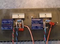
I tidied up the layout and got the powersupply wires a lot shorter and twisted wires together, but still had hum without anything plugged in. So i tried a different wire layout instead, which I found on this forum somewhere dealing with hum, see pic and schematic, no pot.
But this wiring made it abit worse. I have about 10mV AC hum on the outputs without any input and 0.00V (<0.5mV) with the inputs shorted, both channels. What does this mean? It is possible to get <0.5mV without anything plugged right?
With my dac plugged in i have about 3mV AC hum on outputs, which is more than the way it was originally wired.
Any help much appreciated.
Attachments
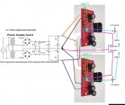
The power wires from the transformer to the rectifier and smoothing capacitors must be twisted pairs.
Now series connect the two PSUs.
The power wires from the combined PSUs must be a twisted triplet to the amplifier.
The Zero Volts in this twisted bundle must connect to the Power Ground on the amplifier.
It does NOT go to some remote "star".
The inputs to the amplifier must be a twisted pair, or a coax.
The outputs from the amplifier must be a twisted pair.
None of these require connection to a remote "star".
Somewhere in the schematic there should be specified a "connection" between input and output so that the output can obtain a voltage reference to the input.
That is the way you assemble a mono block amplifier.
Get that done first. Test it thoroughly. Understand why all those wires were done that way. Remember that lesson. It gets applied to every amplifier you will build.
AFTER learning that mono wiring,
progress to wiring up a stereo version.
Now you have TWO amplifiers that get connected together at various points. The inputs get connected via the interconnects and the remote stereo Source equipment. Use D.Joffe's HBRR & HBRL to solve that loop current problem.
The Safety Earth also connects the two channels. If this causes a problem because of the direct common connection of two Main Audio Ground (MAG) to the Chassis, then introduce TWO disconnecting Networks between MAG and Chassis.
Last edited:
post36, the sch on the right is misleading, or simply wrong.
The bottom of R3 is shown connected to a common ground symbol. NO !!!!
R3 is the -IN terminal. That goes back the the Source as the Signal Return.
R2 also has a ground symbol. NO!!!!
That too goes back to Source as the signal return.
Remember the signal arrives on a TWO WIRE connection. Signal Hot/Flow and Signal Cold/Return. Both these wires MUST connect to the amplifier.
Last edited:
Thank you AndrewT!
I will have to look into the D.Joffe's HBRR & HBRL thing. The wires between the powersupply and amp board are quite short, but I will try to triplet them. The other wires are twisted in pairs, but I could twist them more I guess. I have shielded mic wire, could I use that for input wires? Seem to remember reading that was not good for some reason.
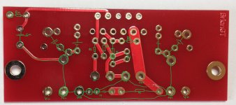
About the R3 (=Ri) and R2 (=RIn) grounding, I think it is correct on the pcb layout, see pic, I've drawn in the placements on the top side. SG connects R2 to R3 and connects them to output ground.
I'm aware that a DC coupled amp can ruin my speakers, but im only using it with my dac, which has caps at output, for now. If I can get it to be better, or as good as my 41Hz amp6, I will install a B1 buffer with caps infront of it. It seems to have some distortion/sibilance compared to amp6.
When I get 0.00V AC hum on outputs when inputs are shorted, does that mean there is nothing wrong with amp, that its just the input wires picking up noise?
I will have to look into the D.Joffe's HBRR & HBRL thing. The wires between the powersupply and amp board are quite short, but I will try to triplet them. The other wires are twisted in pairs, but I could twist them more I guess. I have shielded mic wire, could I use that for input wires? Seem to remember reading that was not good for some reason.
About the R3 (=Ri) and R2 (=RIn) grounding, I think it is correct on the pcb layout, see pic, I've drawn in the placements on the top side. SG connects R2 to R3 and connects them to output ground.
I'm aware that a DC coupled amp can ruin my speakers, but im only using it with my dac, which has caps at output, for now. If I can get it to be better, or as good as my 41Hz amp6, I will install a B1 buffer with caps infront of it. It seems to have some distortion/sibilance compared to amp6.
When I get 0.00V AC hum on outputs when inputs are shorted, does that mean there is nothing wrong with amp, that its just the input wires picking up noise?
Attachments
- Status
- This old topic is closed. If you want to reopen this topic, contact a moderator using the "Report Post" button.
- Home
- Amplifiers
- Chip Amps
- LM3886 DIY amp hum issue