I found the LM3886/3875 circuit with duo-beta at :
http://www.diyzone.net/articles/duo-beta.htm
Is it better than GC???
http://www.diyzone.net/articles/duo-beta.htm
Is it better than GC???
Attachments
circuit duo-beta??
Wont do much good in a single chip application, it will help you dial in the DC offset at idle, but wont be linear with gain.
The circuit will help set idle offset in a bridge parallel application, the circuit posted below has been used by myself with great results for large BPA amps.
Wont do much good in a single chip application, it will help you dial in the DC offset at idle, but wont be linear with gain.
The circuit will help set idle offset in a bridge parallel application, the circuit posted below has been used by myself with great results for large BPA amps.
An externally hosted image should be here but it was not working when we last tested it.
Is it better than GC???
It is a GC. The non-issue of dc offset has been solved. One may wish to further filter the bias voltage though.
DRV sense lines?
analog_se, No I did not notice any sonic improvements, its sounds almost identical to a singal non-inverted chip with no Ci cap except with much more power and control.
The idea was to better match each chip in the circuit without useing .1% or better resistors. My original circuit used 1% metal films and 2% carbon films for the NFB resistors and .15ohm 5% output resistors.
What I did notice was a drastic reduction in idle current per chip as much as 35% down from 80 - 90ma to 45 - 55ma, and the 1watt distortion was also drasticaly reduced, frequency response stayed the same from 15hz to 45khz,but with less role off after 22Khz, the amp gained great amounts of headroom.")
analog_se, No I did not notice any sonic improvements, its sounds almost identical to a singal non-inverted chip with no Ci cap except with much more power and control.
The idea was to better match each chip in the circuit without useing .1% or better resistors. My original circuit used 1% metal films and 2% carbon films for the NFB resistors and .15ohm 5% output resistors.
What I did notice was a drastic reduction in idle current per chip as much as 35% down from 80 - 90ma to 45 - 55ma, and the 1watt distortion was also drasticaly reduced, frequency response stayed the same from 15hz to 45khz,but with less role off after 22Khz, the amp gained great amounts of headroom.
another observation
The amp also breaks the laws of physics it produces more power then it should, and I cannot explain this other then some voltage pumping by product. The amp uses 3*3 lm3875's 6 per channel at +/- 40 volts and produces 342 watts and 496 pulse
PS you have to see and hear it to believe it
The amp also breaks the laws of physics it produces more power then it should, and I cannot explain this other then some voltage pumping by product. The amp uses 3*3 lm3875's 6 per channel at +/- 40 volts and produces 342 watts and 496 pulse
PS you have to see and hear it to believe it
Re: circuit duo-beta??
halo0925
Can the circuit be adapted for the OPA 54xx chip?
halo0925 said:Wont do much good in a single chip application, it will help you dial in the DC offset at idle, but wont be linear with gain.
The circuit will help set idle offset in a bridge parallel application, the circuit posted below has been used by myself with great results for large BPA amps.An externally hosted image should be here but it was not working when we last tested it.
halo0925
Can the circuit be adapted for the OPA 54xx chip?
parts values
Yes I will get one together with parts values and a layout, layout is critical. This is a completed amp pic
Yes I will get one together with parts values and a layout, layout is critical.
This is a completed amp picAn externally hosted image should be here but it was not working when we last tested it.
Re: circuit duo-beta??
Hi halo0925
i'm very intrested in that schematic, what about values? It posted anywhere? Or you can post it?
And that pic of your amp..wow! I don't know what else to say..it amazing..
halo0925 said:Wont do much good in a single chip application, it will help you dial in the DC offset at idle, but wont be linear with gain.
The circuit will help set idle offset in a bridge parallel application, the circuit posted below has been used by myself with great results for large BPA amps.An externally hosted image should be here but it was not working when we last tested it.
Hi halo0925
i'm very intrested in that schematic, what about values? It posted anywhere? Or you can post it?
And that pic of your amp..wow! I don't know what else to say..it amazing..
head_spaz
This circuit is not my design. I found it at:
http://www.diyzone.net/articles/duo-beta.htm
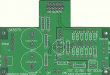
I am a beginner, and I just want to get some ideas about the circuit. This is the PCB. I found it at the diyzone.com :
This circuit is not my design. I found it at:
http://www.diyzone.net/articles/duo-beta.htm
I am a beginner, and I just want to get some ideas about the circuit. This is the PCB. I found it at the diyzone.com :
Attachments
- Status
- This old topic is closed. If you want to reopen this topic, contact a moderator using the "Report Post" button.
- Home
- Amplifiers
- Chip Amps
- LM3886/3875 circuit with duo-beta