Yet, Puffin's amplifier stays cool without a readily apparent means to do so. The really beautiful speakers, while possibly a light load, couldn't keep the amp cool unless there's also a resistor in-series to the amplifier or perhaps 16 ohm speakers.
All my speakers are easy to drive and all my GCs have run at no more than luke-warm temperatures with smallish heatsinks. If a GC is built properly, and it is used with the 'right' speakers, it won't get hot, even using the higher voltages!
Puffin said:Pics of the amp. not pretty, but if I box it up no-one will know !
http://i73.photobucket.com/albums/i239/saxonsex/30v-3.jpg
http://i73.photobucket.com/albums/i239/saxonsex/30v-2.jpg
Oh thank you! Well, don't worry about the appearance. My home stuff looks like that. I'm happy if it fills the house with gorgeous sound.
Analysis:
(least likely to most likely)
Low inductance supply isn't the cause of cooler temperatures because high inductance is pictured. Although minimum capacitance + stronger transformer is a method to run cooler.
This amplifier is even more interesting! Despite high voltage and high inductance at the power circuit, that thing is still running cool! Its not pictured heatsinked to an entire tank of holy water, so, there must be a really interesting electronic explanation instead. Okay, on with the fun. .
The power caps are the compact sort. They are not the type that can be used by car amps speaker output. However, compact caps may have been "augumented" by inclusion of ceramic powder, and the type doesn't require bypassing. This isn't a likely spot for the observed effects, although its not impossible.
The huge industrial bridge rectifier. . . What's the make and model? Its bound to be helping.
")
And, here's the most likely thing. That amp runs from 500uF, not 1000uF. The power ground line is so much longer than the floating ground between the two caps (short thick copper line) that its making rails-to-rails at 500uF, and that will cool down a chip amp, the same as if the total capacitance were actually just 1 pair of 250uF caps. However, the setup pictured would have stronger bass.
That's my guess.
Daniel. I hadn't considered your theory as to the "real world" capacitance seen by the chip. You may be right, I do not have the expertise to comment further.
The bridge rectifier was sourced form Maplin and is the one suggested in the following article. There is no make shown on the can.
http://www.tnt-audio.com/clinica/ssps1_e.html
Very interesting artice. I built very similar PS's for my Gainclones, until another theory was that simplest was best i.e just a tranny and bridge rectifiers.
Hi Puffin! Thanks for your help.
On the caps and grounding, I don't know either. Perhaps AndrewT will happen along and analyze it for us?
I never would have guessed that I should try more bridge rectifier than necessary for the application. However, it seems that I really should try that one.
I hope its okay if I ask for one more favor? Since the article won't load, I sure would like a link to that bridge rectifier at Maplin's site. Maybe its one of these: http://www.maplin.co.uk/module.aspx?ModuleNo=19088&doy=22m3
Ah, but which one?
http://www.maplin.co.uk/module.aspx?ModuleNo=19088&doy=22m3
KBPC2504 is the one I am using.
Some pics of your builds would be welcome.
KBPC2504 is the one I am using.
Some pics of your builds would be welcome.
Picture attached
Its this one:
http://www.alliedelec.com/Search/ProductDetail.asp?SKU=266-0047
Pictures? Okay. Its stuff that I'm playing with right now.
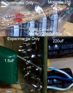
The big poly cap pictured (edit3: its pictured below in the attachment) in the power circuit has the nifty effect of much extra detail; however, I'm certain that its value is the wrong size and that the size is reliant on factors that I couldn't calculate. Anyway, it was just the first try, which is why its tacked on like that. There's a misprint. That cap is actual 2uF.
On the 220uF caps pictured, if I replaced those with 2200uF, the amplifier will get eleven times warmer, experience trouble with driver control, and it doesn't repay this trouble with additional bass. Curious.
At this same position, 470uF was very powerful on the bass and extraordinarily clear (without the little green helper). Unfortunately 470uF made shouting midrange.
There seems to be a lot of interesting sonic tuning available at the power circuit. Some of the options have a dramatic effect on heatsink requirements too.
Edit: The big 3 big soldered lines on the power supply board are multi conductor 16 ga. The caps and diodes make direct contact with the copper fibers under pressure, before soldering. The solder only holds things in place and it is also inside (inbetween) the copper fibers. So, that isn't just solder sitting on top. I was thinking that the method was possibly less inductive.
That turned out to be true.
This and the 220uF decoupling caps have verifiable advantages; however, the rest is a tinkertoy.
Edit2: Not shown are 100nF MKP at the chip pins because the 220uF caps that I used have a failure mode at high frequencies (and need the extra help).
Its this one:
http://www.alliedelec.com/Search/ProductDetail.asp?SKU=266-0047
Pictures? Okay. Its stuff that I'm playing with right now.
The big poly cap pictured (edit3: its pictured below in the attachment) in the power circuit has the nifty effect of much extra detail; however, I'm certain that its value is the wrong size and that the size is reliant on factors that I couldn't calculate.
Anyway, it was just the first try, which is why its tacked on like that. There's a misprint. That cap is actual 2uF. On the 220uF caps pictured, if I replaced those with 2200uF, the amplifier will get eleven times warmer, experience trouble with driver control, and it doesn't repay this trouble with additional bass. Curious.
At this same position, 470uF was very powerful on the bass and extraordinarily clear (without the little green helper). Unfortunately 470uF made shouting midrange.
There seems to be a lot of interesting sonic tuning available at the power circuit. Some of the options have a dramatic effect on heatsink requirements too.
Edit: The big 3 big soldered lines on the power supply board are multi conductor 16 ga. The caps and diodes make direct contact with the copper fibers under pressure, before soldering. The solder only holds things in place and it is also inside (inbetween) the copper fibers. So, that isn't just solder sitting on top. I was thinking that the method was possibly less inductive.
That turned out to be true.
This and the 220uF decoupling caps have verifiable advantages; however, the rest is a tinkertoy.
Edit2: Not shown are 100nF MKP at the chip pins because the 220uF caps that I used have a failure mode at high frequencies (and need the extra help).
Attachments
Okay, so now I'm confused. I was planning on using a 300va toroidal with 30v outputs, giving 45vdc at the PS outputs for a LM3875 build. Is max. voltage 94, or 45, as someone mentioned?
Again, just have a look at the datasheet.
From page 3:
Absolute Maximum Ratings (Notes 1, 2)
Supply Voltage |V+| + |V−| (No Signal) 94V
Supply Voltage |V+| + |V−| (Input Signal) 84V
Operating Ratings (Notes 1, 2)
Temperature Range
TMIN ≤ TA ≤ TMAX −20C ≤ TA ≤ +85C
Supply Voltage |V+| + |V−| 20V to 84V
Note: Operation is guaranteed up to 84V, however, distortion may be introduced from the SPiKe Protection Circuitry when operating above 70V if proper thermal considerations are not taken into account. Refer to the Thermal Considerations section for more information. (See SPiKe Protection Response)
From page 4:
Note 1: Absolute Maximum Ratings indicate limits beyond which damage to the device may occur. Operating Ratings indicate conditions for which the device is functional, but do not guarantee specific performance limits. Electrical Characteristics state DC and AC electrical specifications under particular test conditions which guarantee specific performance limits. This assumes that the device is within the Operating Ratings. Specifications are not guaranteed for parameters where no limit is given, however, the typical value is a good indication of device performance.
- Status
- This old topic is closed. If you want to reopen this topic, contact a moderator using the "Report Post" button.
- Home
- Amplifiers
- Chip Amps
- LM3875 Voltage