Hi everyone, I just finished building my LM3875 gainclone (Peter Daniel's kit), and I have a problem with the left channel. First off, when I checked the voltages at each of the pins of the LM3875, when I got to pin 4 (the V- connection), I got an arc. Everything still works fine tough. At any rate, my voltages are fine at the points they connect to the amp PCB (+/-36V DC) , and all the other pins are fine. Also, when I turn up the volume (increase the power) too much, I get overheating and I believe the op amp's Spike protection kicks in (not sure, all I know is the sound gets very static-y (but you can still make out the music), and messes up the picture on my LCD monitor). Keep in mind, this is only the left channel; the right channel seems to work flawlessly. Can anyone clue me in on what's happening? 🙁 Oh, also, I looked over the solder connections on the PCB, and everything looks alright there, and it doesn't look like anything is contacting something it shouldn't be.
I was thinking it may be a heat dissipation issue, but then why would it only happen on one channel when both channels are constructed nearly identically, and also, then why is pin 4 arcing?
My othet thought was a faulty op amp, but then why does it work seemingly fine until I turn the volume past a certain point?
If it helps any, my heat sinks are two 3" by 4" finned aluminum pieces bolted to my 2mm thick aluminum chassis, and the op amp is then attached to the chassis on the other side of the heat sink, with a thin thermal conducting film (I believe it's called Thermasil) in between the op amp and the chassis.
could be a bad chip but check for solder splashes/shorts. Post up some pics, close ups.
i dont think one channel would get hot more then the other. what kind of transformer are you using?
i dont think one channel would get hot more then the other. what kind of transformer are you using?
The transformer is a 250VA Avel Lindberg with dual 25V secondaries. I'll try and get some pics later this evening.
Actually, it seems okay as long as I am playing something with it (the left channel still gets warmer than the right one though). However, when the sound stops, it starts warming up.
Actually, it seems okay as long as I am playing something with it (the left channel still gets warmer than the right one though). However, when the sound stops, it starts warming up.
I noticed this morning that the left channel has more gain as well (at least, it plays louder than the right one). Therefore, I thought I may have switched the resistors, but they seemed correct. Any thoughts?
so you have the correct resisters in place? feedback resister? its either something very simple being over looked or the chip is defective. double check those resisters.
I checked the resistors, and they match up (the left and right channels each have the same resistors in the same places), and I know that I got the right channel correct.
In case anyone was wondering, my problem has been at least partially fixed. It turns out I had a short in the coax cable that connected the right channel's RCA input jack to the 10k pot, which explains why the right channel was quieter. I'm also going to remove the heat sinks and put thermal paste in between them and the chassis to aid heat conduction, and I'll probably replace the Thermalsil with thermal paste as well, since the Thermalsil pieces don't cover the whole surface of the chip. In addition to this, after looking closer, some of my solder connections are pretty bad, so I'm going to go over those again (that's what happens when you're up at 3am trying to solder with an iron where only one side of the tip heats up...yeah, figure that out 😕 ).
cjv998 said:(that's what happens when you're up at 3am 😕 ).
no kidding. good to hear you figured that out. have fun
Okay, I re-ran all my signal cables, and used thermal paste like I mentioned above (which helped heat transfer to the heat sinks a ton, by the way; I'm impressed), but the left channel op amp still gets very hot. A minute or two after being turned on, it's very hot to the touch, whereas the right channel will still be almost room temperature. I'm thinking I need a new op amp for the left channel (I probably messed this one up when I got the arcing by pin 4, which is definitely scorched black now), can anyone confirm this? Also, does anyone know where I can get a new feedback resistor (22k Phoenix SFR16S that comes with Peter Daniel's basic kit, I couldn't find them on Digikey or Mouser)? I don't need one, but it would be easier to solder on to the new chip if I have longer leads.
P.S.: I'll hopefully get pictures tonight, I have to wait for my batteries to charge.
P.S.: I'll hopefully get pictures tonight, I have to wait for my batteries to charge.
Maybe you could cut off the chip pins that that resistor is soldered to, near the chip body, and then de-solder (from the board) the portions of the pins that have the resistor soldered to them, cut off the tips of the old pins, and solder all of that to the new chip's pins.
- Tom Gootee
http://www.fullnet.com/~tomg/index.html
- Tom Gootee
http://www.fullnet.com/~tomg/index.html
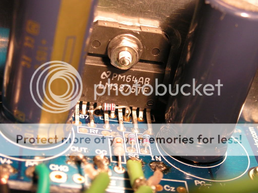
Finally got some pictures, and I've sorted out two of the better ones. My camera isn't one of the slim "cigarette case" style cameras, it has a fixed barrel for the lens, and is therefore pretty bulky, so the pictures were rather difficult. However, using macro mode and using a halogen light instead of the flash (in the more closeup of the two pictures) seemed to help a little. Anyway, enough of my rambling, the pictures are attached below, and you can see, especially in the second picture, that pin 4 (and the solder pad) is nice and black.
Please excuse the overall poor soldering job (and poor case construction as well), as this is my first time doing anything involving soldering more than one or two points, and my first time making extensive use of power tools (for the case). I definitely started to get the hang of things towards the end, however. 😉
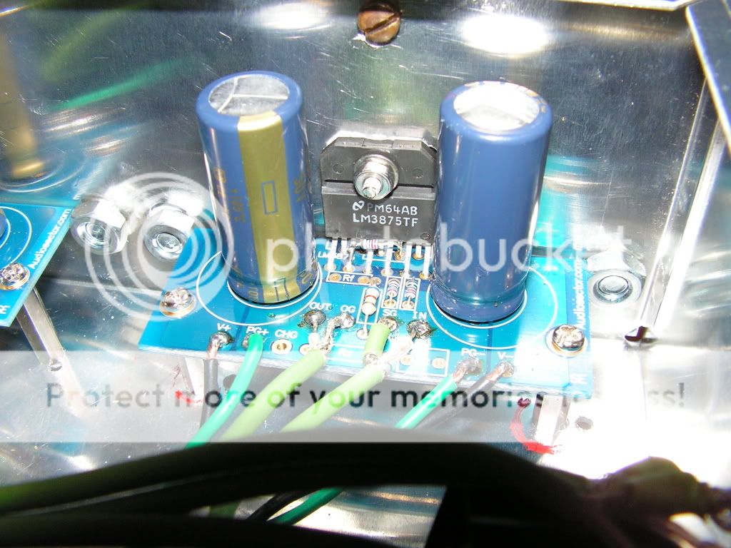
By the way, if there's a more preferred method for posting images than this, let me know. I see how this could be irritating to people running at a screen resolution of 1024x768 or less. Photobucket is just convenient for me because it resizes my images, so I don't have to mess with it.
Please excuse the overall poor soldering job (and poor case construction as well), as this is my first time doing anything involving soldering more than one or two points, and my first time making extensive use of power tools (for the case). I definitely started to get the hang of things towards the end, however. 😉
By the way, if there's a more preferred method for posting images than this, let me know. I see how this could be irritating to people running at a screen resolution of 1024x768 or less. Photobucket is just convenient for me because it resizes my images, so I don't have to mess with it.
I replaced the chip in the offending channel yesterday, and now everything seems to be working perfectly; no overheating at all. 😀
Okay, the problem is back, same as before. I turned up the amp more than I intended to a few days ago, and now the left channel gets hot and static-y again. I assume I need a new chip, but is there some underlying problem I'm missing here? Please help, thanks!
Well, those chips run warmish at +/- 36v and need adequate heat sinking. The chip needs to mount against a flat surface with minimal gaps so it only requires a thin film of HS grease (but use plenty). Check to make sure the relatively thin chassis wall isn't warped or bent from the mounting of the outer heat sinks; and that there weren't any burrs left where you drilled the holes that might allow the chip to be pushed away from the surface. It might be possible to cut a window through the chassis and mount the chip directly to the HS.
Oscillation isn't usually a problem with these kits (but it may depend on many of factors) but will cause the chip to run hotter. You could try the R-C network (aka. Zobel) on the output. This is the Rz and Cz on the boards. Peter may have included these parts with the kit.
What speakers/impedance are you driving with these amps? At +/- 36v I wouldn't want to drive speakers that had low impedance dips.
Also, the data sheets are a great source of information.
Good luck.
Scott
The speakers are standard 8 ohm bookshelf models (Paradigm Mini Monitor v5's). The chip is still snug against the case, which is still snug against the heat sink, and thermal paste is between both interfaces. At any rate, I think I blew up another chip when I turned up the volume too high, too quickly. It sounds like oscillation is my issue. It takes a few minutes to get hot, but when it does, it's VERY hot. Only the left channel still, too; the right channel has never given me any trouble at all. My DC offset stays constant though (-7.6mV on the left channel, and +30.6 on the right). So I need yet another chip, only problem is a $6 chip becomes an $18 chip on Digikey after shipping and handling. I may see if I can go in with one of my professors that orders from Digikey frequently to avoid that problem.
Good eyes; it looks like it. I'll have to look over the PCB carefully when I take it out to replace the chip, and make sure to clean up all of that. Thanks.
It looks like youre using some kind of coaxial cable for the speaker output wiring.
BAD IDEA. This stuff is normally low current, and also has quite a bit of capacitance, which could very well cause oscillation. Replace this cabling with standard cable. It's especially dodgy as the zobel components (Rz and Cz) aren't fitted.
I'd fit the zobel parts, but not on the PCB. Fit 10 ohms 1W and 100nF in series across your speaker terminals. This will help stabilise the amplifier with long runs of cable.
Also, clean up that soldering. The wires should go through the hole. There should be very little exposed wire above - just enough to get a solder joint, no more.
Treat yourself to a new iron, buy some stripboard and a big bag of cheap resistors and solder till your fingers bleed. Practice makes perfect, or so they say.
- Status
- Not open for further replies.
- Home
- Amplifiers
- Chip Amps
- LM3875 gainclone problem