Re: ... and another thing ...
to be on the safe side i will use your idea to drop the voltage, as i have some MUR diodes with two diodes in one package. but i have one query. can this daisy chain of diodes be put just after the rectifier and before the filter caps or i have to put them after the filter caps? which one is better?
thanks
FastEddy said:Here is a neat trick however ... you can use a daisy chain of diodes to "knock down" the incoming voltage = each diode = 0.6 VDC throw away = 10 diodes = 6 VDC down. [/B]
to be on the safe side i will use your idea to drop the voltage, as i have some MUR diodes with two diodes in one package. but i have one query. can this daisy chain of diodes be put just after the rectifier and before the filter caps or i have to put them after the filter caps? which one is better?
thanks
Re: Re: ... and another thing ...
Before the cap they have to conduct the very high charging pulses into that cap. After the cap they only have to conduct the load current. The latter makes life easier for those caps and gives less possible interference of pulsed current that *may* radiate depending on the layout.
Jan Didden
Roushon said:
to be on the safe side i will use your idea to drop the voltage, as i have some MUR diodes with two diodes in one package. but i have one query. can this daisy chain of diodes be put just after the rectifier and before the filter caps or i have to put them after the filter caps? which one is better?
thanks
Before the cap they have to conduct the very high charging pulses into that cap. After the cap they only have to conduct the load current. The latter makes life easier for those caps and gives less possible interference of pulsed current that *may* radiate depending on the layout.
Jan Didden
extra parts ...??
Re: snubbed regulator in your circuit diagram ...
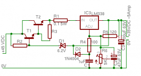
1) I never understood why the value of R1 & R2 was so low in this circuit (2.2K ohms) .... it bleeds off the power supply rails continuously = wasting power and generating heat. (This circuit would fail current production power supply restrictions in Europe and soon, here in the states. = an environmentally incorrect design, etc .... A value about 5 times greater, 10K to 22K ohms would suffice ... or none at all).
2) Likewise, I believe that R3 & R4 should be 910R ohms (instead of 91R ohms) and R5 & R6 should be 22K ohms (instead of 2.2K ohms) ... saving a little more in wasted heat, etc. I would also suggest that for audio work that R3, R4, R5 & R6 be metal film type and held to precision of +/- 2% or +/- 1%. (1/8 watt rating is OK here if R5 & R6 >= 10K.)
3) For capacitors C3, C7, C4 & C8, I would recommend the use of plastic (polystyrene) or comparable "audiophile" quality capacitors ... most especially at C4 & C8. (SoniCaps ?). These capacitors are used here as "snubbing" caps, reacting to and filtering off the higher frequencies and "popcorn" noise associated with fixed voltage regulators and RF from external sources.
4) I always add a Ferrite Bead to the output legs and ground legs of these kinds of linear supplies ... especially if intended for a sperate enclosure. ( http://en.wikipedia.org/wiki/Ferrite_bead )
5) Transformer: if independant 30 VAC secondary type is unavailable, then a "center tap", +/- 28 to 30 VAC secondary may be used (although some here might quibble about retaining the "split supply" nature of the original). The center tap can be connected directly to "G" or anywhere upstream of "G" and downstream of the (-) negative LM338 at D2.
6) If output power is expected to exceed ~ 40 watts (output >= 40 VA) ... then a heat sink should be added to both LM338 regulators. If close to the maximum rating of the transformer (200+ VA) then the heat sink(s) on the LM338 should be quite large indeed.
(Alternate part number for LM338 = pin for pin substitution = uA7805, although some here feel that this substitution will be noisier and is of older design.)

Re: snubbed regulator in your circuit diagram ...
1) I never understood why the value of R1 & R2 was so low in this circuit (2.2K ohms) .... it bleeds off the power supply rails continuously = wasting power and generating heat. (This circuit would fail current production power supply restrictions in Europe and soon, here in the states. = an environmentally incorrect design, etc .... A value about 5 times greater, 10K to 22K ohms would suffice ... or none at all).
2) Likewise, I believe that R3 & R4 should be 910R ohms (instead of 91R ohms) and R5 & R6 should be 22K ohms (instead of 2.2K ohms) ... saving a little more in wasted heat, etc. I would also suggest that for audio work that R3, R4, R5 & R6 be metal film type and held to precision of +/- 2% or +/- 1%. (1/8 watt rating is OK here if R5 & R6 >= 10K.)
3) For capacitors C3, C7, C4 & C8, I would recommend the use of plastic (polystyrene) or comparable "audiophile" quality capacitors ... most especially at C4 & C8. (SoniCaps ?). These capacitors are used here as "snubbing" caps, reacting to and filtering off the higher frequencies and "popcorn" noise associated with fixed voltage regulators and RF from external sources.
4) I always add a Ferrite Bead to the output legs and ground legs of these kinds of linear supplies ... especially if intended for a sperate enclosure. ( http://en.wikipedia.org/wiki/Ferrite_bead )
5) Transformer: if independant 30 VAC secondary type is unavailable, then a "center tap", +/- 28 to 30 VAC secondary may be used (although some here might quibble about retaining the "split supply" nature of the original). The center tap can be connected directly to "G" or anywhere upstream of "G" and downstream of the (-) negative LM338 at D2.
6) If output power is expected to exceed ~ 40 watts (output >= 40 VA) ... then a heat sink should be added to both LM338 regulators. If close to the maximum rating of the transformer (200+ VA) then the heat sink(s) on the LM338 should be quite large indeed.
(Alternate part number for LM338 = pin for pin substitution = uA7805, although some here feel that this substitution will be noisier and is of older design.)
wine&dine said:>
Diode drops are fine when you need a small voltage drop. In Roushon's case, an extra transistor is much safer. See http://www.national.com/an/LB/LB-47.pdf for a circuit.
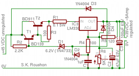
following the circuit in the above page a schematic is designed (attached). my aim is to safeguard LM338 from possible high in-out voltage difference (in case of output short) . the plan is to keep this difference fixed around 6v. please give me your suggestion for the points below.
1. value of the darlington pair transistors.
2. is only one transistor enough instead of the darlington pair?
3. value of the resistors.
4. also if the other resistor values are OK.
or any other concern....
Attachments
FastEddy said:
As previously mentioned the uA78xx series can be "stacked", all pins connected in parallel, for just about any current rating you want.
This is new - is it in the data sheet? Seem to have missed that!!
Fasteddy, where did you get this info? Thanks!
Stacked 78xx ??
fasteddy: " ... the uA78xx series can be "stacked", all pins connected in parallel, for just about any current rating you want. ..."
clem-o: " ... This is new - is it in the data sheet? Seem to have missed that!! Fasteddy, where did you get this info? Thanks! ..."
I have been using this scenario since about 1980 = parallel 78xx and 79xx. When I built my first computer, I used ten (10) Fairchild uA7805 in the TO-3 can in parallel on two large heat sinks to power the bus, I/O & processor boards in a rack of S-100 bus boards. In the supply there were also two (2) uA7812 in parallel, one (1) uA7912, 0ne (1) uA7905 on the sinks. Result = fairly clean power + 5 VDC @ ~50 Amps "rating", - 5 VDC @ ~ 5 A., +/- 12 VDC @ 10 A. and 5 A. respectively. No problems, total load was actually ~ 25 Amps, mostly on the +5 VDC side, heat sinks ran at about +5 to +15 deg. F. above ambiant. I still have this supply and it still works as does the whole computer. (The -78xx in the TO3 can had a rating of 5 Amps back then, each, which was a little generous as it implied an "infinite" heat sink, so 1/2 power loading for thermal reasons was/is a good idea.)
I have built a number of other digital and analog projects using "stacked", parallel 78xx including a bench supply with four (4) each uA7815 and four (4) uA7915 = +/- 15 VDC @ max of ~20 Amps "rated", each rail, although I have seldom used it to do more than 2 A. loads.
Please note that others posting about the original, primary question ... that the LM338 is a better regulator than the old uA78xx series = better noise filtering, etc. ... and I am not sure that it is a good idea to "stack" or parallel the LM338 ...
")
maybe this application paper from National can be of some use:
Linear Brief 47:
High Voltage Adjustable Power Supplies
http://www.national.com/an/LB/LB-47.pdf#page=1
The output is at Max 160 Volt adjustable and 25 mA.
Circuit is for LM317HV High Voltage, and this is 'a brother' of LM338 and LM317
If you want to BROWSE all National Application Notes, audio or other,
use this link:
http://www.national.com/apnotes/
lineup
lineup said:
maybe this application paper from National can be of some use:
Linear Brief 47:
High Voltage Adjustable Power Supplies
http://www.national.com/an/LB/LB-47.pdf#page=1
The output is at Max 160 Volt adjustable and 25 mA.
Circuit is for LM317HV High Voltage, and this is 'a brother' of LM338 and LM317
If you want to BROWSE all National Application Notes, audio or other,
use this link:
http://www.national.com/apnotes/
lineup
well, this is exactly the source Wine&Dine pointed out to me, i mentioned this two posts back. and the design around LM338 is based on this notes for LM317.
thanks and regards
Hi Jeff,
the 34vac will give after the rectifiers and
capacitors 34 x sqrt 2= 48vdc (approx). So if you use the
same component value as in my case the circuit will
work perfectly alright.
I do not remember if I took closeup
pictures of the finished project. I will check my camera
and post. But I remember taking picture of the whole
amplifer, so by zooming you can see. Will open the amp
in a week or so for some up gradation then will post a
detail picture.
Thanks
Roushon.
Hi Jeff,
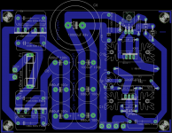
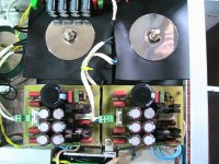
There is one photo of the PS I have. It is attached. There are four
PS boards. One is placed on another with long spacers (not seen in the
pic). I hope it helps.
Roushon
Roushon,
Again thank you for sharing your work.. One more question... there is what appears to be a 47K Ohm 1watt resistor sitting overtop of the BD139 Transistor which isn't shown in the schematic... Was this a late addition? and onto which traces does it connect?
Jeff
- Status
- This old topic is closed. If you want to reopen this topic, contact a moderator using the "Report Post" button.
- Home
- Amplifiers
- Power Supplies
- LM338 regulator InputMax voltage..