if you get thru Rod's info there's more: http://www.diyaudio.com/forums/head...capacitors-opamp-power-rails.html#post2872703
bumping this up for another check as i'm bound to have got something wrong 
its not for audio so not needed to be super dooper.
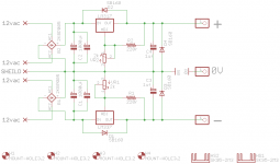
Schematic

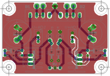
Board

BOM
C1-2 1000uf, Aluminium Electrolytic
C3-4 1UF Tantalum
R1-2 220r Metal Film
VR1-2 2k Variable Resistor
D1-4 1A-60V Schottky Diodes SB160
BR1-2 2A-50V Bridge Rectifiers
LM317 Positive Regulator
LM337 Negative Regulator
its not for audio so not needed to be super dooper.
Schematic

Board

BOM
C1-2 1000uf, Aluminium Electrolytic
C3-4 1UF Tantalum
R1-2 220r Metal Film
VR1-2 2k Variable Resistor
D1-4 1A-60V Schottky Diodes SB160
BR1-2 2A-50V Bridge Rectifiers
LM317 Positive Regulator
LM337 Negative Regulator
Hello again.
That looks fine
I discovered recently that it's necessary to use fast diodes or the rapid charging of the output capacitors can cause the regulators to lock up. You have used fast diodes so there should be no problem. Worth baring in mind though
Also reread what AndrewT posted
That looks fine
I discovered recently that it's necessary to use fast diodes or the rapid charging of the output capacitors can cause the regulators to lock up. You have used fast diodes so there should be no problem. Worth baring in mind though
Also reread what AndrewT posted
12Vdc from a regulated supply usually works with a 12Vac transformer. This rule Vac ~ = reg Vdc holds for voltages from ~10v to ~30vanother question. given the above schematic and an input of 12vac what sort of max dc voltage can i expect on the output?
guess i should ask what size of secondary's do i need for 12vdc output with a little headroom?
As you go higher the AC voltage can be a bit less than the required DC voltage.
As one goes lower, one needs to use a slightly higher Vac as the supply, say ~7Vac for that reg 5Vdc.
The exception is a Shunt style regulator where you need to take account of the extra voltage drop across the current limiter that must precede the Shunt regulator. Most 12Vdc shunt regulators will work with a 15Vac transformer.
Very neat. I've only ever built them on vero....
thanks Scott.
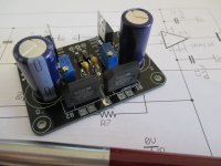
well i wired it all up switched it on and no bang
that went well so i then tested for voltage by probing 0V + and got 6.9v. i then probed 0V - and got -7.2v. i haven't twiddled the pots yet but things look promising
i dont have a scope so cant tell you what sort of voltage is coming out. all i know is its DC... lol
am i chuffed.. you bet
ok just measured the trafo and its 14vac supposed to be 12... lol so its not that
so i go down not up on the resistor.. silly me
as for how high the positive will go. i have no idea as not gone past the 12vdc.
i'll dig around in the resistor bin and see what i have thats around 120-200r
thanks again
TBH i could just use 11.5vdc but i would rather get it right. in a way i'm glad its not worked perfect as then i dont learn anything.
- Status
- This old topic is closed. If you want to reopen this topic, contact a moderator using the "Report Post" button.
- Home
- Amplifiers
- Power Supplies
- LM317/337 dual supply
