Yes i'm Canadian so it's 110V 60Hz here.
I think I'm going with the Inglot because it is only 44$ US ~47$ CAD
This transformer output 30VAC ?
I have a RS 605 Bridge it's ok for the schematic above ?
Thanks
I am not sure which transformer you are referring to. The Inglot I linked is ~$13 plus shipping and the Stancor is about the same.
The RS 605 would be a good. Nice design choice because it can handle more current then either of the transformers can output or the amplifier can draw in normal use.
I've found this Transformer
It's good ? Because only 8$ CAD Shipping
Thanks !
PS: Just to be sure, all my speaker are 4 ohms is it ok with the BTL ? For the sub you said 8 ohms but would it work too with 4 ohms ?
It's good ? Because only 8$ CAD Shipping
Thanks !
PS: Just to be sure, all my speaker are 4 ohms is it ok with the BTL ? For the sub you said 8 ohms but would it work too with 4 ohms ?
Last edited:
50VA is small for a power amplifier.
It would suit a total of 25W to 50W of maximum amplifier power.
But a small transformer has high regulation. Around this size expect about 10% to 12% transformer regulation.
i.e. a 115:15Vac transformer will give out 127/115*1.12*15Vac when unloaded or ~18.5Vac
It would suit a total of 25W to 50W of maximum amplifier power.
But a small transformer has high regulation. Around this size expect about 10% to 12% transformer regulation.
i.e. a 115:15Vac transformer will give out 127/115*1.12*15Vac when unloaded or ~18.5Vac
Power Transformers
Still pricey for something that would work. 67-1245
I didn't download their full catalog. $30.85 + whatever shipping would be. Got to be less then $14 for shipping.
4 Ohms speakers will be fine for every conceivable power supply.
Not exact because speakers aren't just resistance. Plug the values of 30V and 4 Ohms into this Online Conversion - Ohm's Law Calculator
A 24 VAC transformer will be rectified to 33.6V/+-16.8V. Amplifiers are perfect, with a 33.6V supply they may only put out 25V to the speakers, but you have plenty of headroom.
There used to be some odd stuff in the early days of car audio. Since power supply was limited to 12V, they used to make 2 Ohm speaker systems. Heck, they may still do. Same thing for tube amps and PA speakers but going the other way i.e. 16 Ohm. 99% safe with home systems assuming 4-8 Ohms nowadays but best to check.
Hey !
This 100VA transformer can be ok ?
Digikey is a partner of my university where i do my bachelor in electrical engineering, so shipping is free")
This 100VA transformer can be ok ?
Digikey is a partner of my university where i do my bachelor in electrical engineering, so shipping is free
Use LM3886, single supply circuit and make the supply with your present transformer wired for one single +65V rail. Not optimal, but neither is your situation. Since the application is very low criticality, it should work fine.
http://www.radio-electronics.com/info/circuits/diode-rectifier/two-diode-full-wave-rectifiers.php
Voltages are spot on for that chip, unless you have 4 ohm speakers in which case use the TDA7294 which has some voltage headroom.
Of course, you could also consider the LM4702 driver+BJT transistor solution, where no trickery will be required. I sense however, it will be overkill for that puny speaker. So will the 3886, but at least the voltage will hold up right.
Last edited:
Use LM3886, single supply circuit and make the supply with your present transformer wired for one single +65V rail. Not optimal, but neither is your situation. Since the application is very low criticality, it should work fine.
Two Diode Full Wave Rectifier Circuit :: Radio-Electronics.Com
Voltages are spot on for that chip, unless you have 4 ohm speakers in which case use the TDA7294 which has some voltage headroom.
Of course, you could also consider the LM4702 driver+BJT transistor solution, where no trickery will be required. I sense however, it will be overkill for that puny speaker. So will the 3886, but at least the voltage will hold up right.
So clearly what should I do

If i buy this transformer(or this) is it ok with the LM1875 kit ?
Because i'm a little bit confused with all these transformers
Thanks
Because i'm a little bit confused with all these transformers
Thanks
Last edited:
The 100VA will give about +24Vdc when lightly loaded.
Is the 1875 safe with this supply?
1875 can handle up to +-30V, so it should be fine.
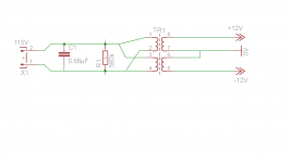
C1 must be an X rated capacitor. Either X1 or X2.
You need a fuse in the live line immediately after the incomer and before any switch or other component. In the BS1362 plug top, that we use in the UK, there is a fuse fitted. This can be used in place of the equipment fuse.
You need a fuse in the live line immediately after the incomer and before any switch or other component. In the BS1362 plug top, that we use in the UK, there is a fuse fitted. This can be used in place of the equipment fuse.
- Status
- This old topic is closed. If you want to reopen this topic, contact a moderator using the "Report Post" button.
- Home
- Amplifiers
- Chip Amps
- LM1875