Tda2050 should work on that pcb. There is an option for BTL. I'm not sure if you need that or not. More knowledgeable person can definitely help you.
BTL is for mono right? If I want to run BTL, I should solder a 22k resistor there, rite?
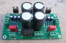
I have extra boards and 4 pieces of TDA2050 with me.
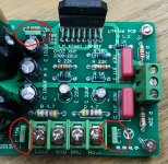
Is this using tda2050?You are probably right. But I don't know if you have to connect those two points with a wire.
Edit: You don't need to short them. I have found a completed pcb.
Ok.thanksYes. Lm1875 and tda2050 are pin compatible.
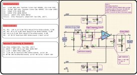
This sch does not differentiate between Signal Return and Speaker Return+Power Ground.You can follow this one:
DIY TDA2050 Hi-Fi Chip Amplifier (chipamp)
Also I have attached a schematic from the datasheet.
It omits the RF attenuator at the input and omits the damped Output Inductor.
The ratio C1:C2 is wrong.
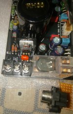
Noob question. Output of the board only has R out, ground, l out as you can see from the picture. Should negative ports of both the speaker be connected with the common ground?
Never mind. Sorted out.
It is C2 that desperately needs to be much bigger in relation to C1.In the past few weeks I've built some of these and they are working great! (C1 may be a bit bigger)
>
It is C2 that desperately needs to be much bigger in relation to C1.
I totally agree.
Feedback pole = 15.9 Hz
Input pole = 4.9 Hz
Perfect combination for distortion. It is the input pole that must always be the dominant pole, preferably by a factor of 10. This way the feedback capacitor has virtually no effect on the performance of the circuit.
C2= 100 uF moves the feedback pole down to 1.59 Hz. In practice this works fine with an input pole of 4.9 Hz, since both poles are low enough to be effectively unobtrusive.
With C2 so large, you want to add anti-latch up (clamp) diodes to C2.
I see so many circuits that ignore this basic principle. To me it's a no brainer.
I have been giving this advice for years, but few if any bother to read it.
I picked it up from a Member many years ago and tried it in a couple of amplifiers and it proved to me that it was the right way to do it.
Having used the advice and having gained that knowledge, when I read D.Self and others on the distortion effects of capacitors (when used as filters), it all falls into place.
There are some who disagree.
when I read D.Self and others on the distortion effects of capacitors (when used as filters), it all falls into place.
Exactly. And it's especially true for the typical capacitor we would use in this application.
There are some who disagree.
With empirical science?
This makes a measurable and sometimes audible difference. Is the sky green? (Syd Barret aside
 )
)In summary, the amount of distortion a capacitor can introduce into a circuit is directly proportional to the ratio of the capacitor's impedance to the impedance of the network it's in.
Apply this principle with C2 = 10 uF, f = 20 Hz.
Now apply this principle with C2 = 100 uF, f = 20 Hz.
Any questions?
Apply this principle with C2 = 10 uF, f = 20 Hz.
Now apply this principle with C2 = 100 uF, f = 20 Hz.
Any questions?
- Status
- This old topic is closed. If you want to reopen this topic, contact a moderator using the "Report Post" button.
- Home
- Amplifiers
- Chip Amps
- LM1875 or TDA7498 For good clean sound (Boards shown in the post)