...it's easy to replicate the Howland CP including the negative feedback network and eliminate this issue if necessary. The non-inverting input of both Howlands will then be driven from the (common) Deboo integrator node.
Here's the schematic with that change incorporated. Now both the output chipamps are independent without a master-slave relationship. The arrangement works even with mismatched local feedback networks (as shown), but the current sharing will be unbalanced by a large factor - maybe 100% or more for a resistance mismatch of 5%. This doesn't seem to hurt the sonics much - H3 is higher when the local feedback networks aren't matched, but still about 30 dB below H2 in the circuit shown.
Both the output chipamps must be matched closely, however - their dominant poles must match closely, or else there will be a phase shift between the two, leading to spikes in crossover current through Rs1 and Rs2. One way to ensure this is to pick them from the same batch, or use a device like the LM4780 which (hopefully) has two matched die in the same package. With some changes to rail voltages and closed-loop gain, it should be possible to use the LM4780 as a drop-in replacement for the 2 x LM1875 in the simulation schematic for power output in the range of 80-100W/channel.
Attachments
@gootee: Thanks for the links - I'll try out the square-wave and slew rate tests in due course.
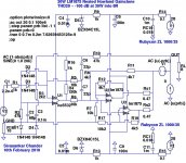
Meanwhile, I managed to stabilize it further - the tweaked compensation in the schematic shown below allows it to drive a 10 uF || 8 ohm load stably. The output waveform stays sinusoidal up to about 200 mW output, after which the LM1875 goes into current-limiting and the waveform becomes more or less triangular. In any event, it does not show any HF instability, either before or after current limiting sets in.
The tradeoff? Another ~10 dB of THD20 has to be given away, taking it to about -110 dB - it's still worthwhile, IMHO.
Shown below is the modified simulation schematic including the 8R || 10 uF load, the loop gain plot with the 8R || 10 uF load, and the output waveform FFT plot at 200 mW into 8R || 10 uF.
This amplifier is interesting indeed; however, since LM1875 has no need of such assistance in practice, why not make a nested LM3886?
Amplifiers with higher output potential have greater need of lower distortion.
This amplifier is interesting indeed; however, since LM1875 has no need of such assistance in practice, why not make a nested LM3886?
Amplifiers with higher output potential have greater need of lower distortion.
Agreed - the LM4780 or 2 x LM3886 per channel are the ideal candidates for this topology. My guess is that they will just work fine (maybe with minor tweaks to the compensation) in this topology without significant alteration, but it has to be prototyped and auditioned to validate the concept. There doesn't seem to be a reliable SPICE structural model for the LM3886 on the web.
Agreed - the LM4780 or 2 x LM3886 per channel are the ideal candidates for this topology. My guess is that they will just work fine (maybe with minor tweaks to the compensation) in this topology without significant alteration, but it has to be prototyped and auditioned to validate the concept. There doesn't seem to be a reliable SPICE structural model for the LM3886 on the web.
If you could model LM4780 with one channel not used, then you have modeled LM3886.
Another thought: It "would be nice" if the project were easily do-able. Therefore, a "simple version" would be nice to look at, especially if it were closely related to a more complex version, so that these differences (any added complexities) could be isolated and compared.
Working with the nesting idea, I think that adding at the preamp is higher fidelity than subtracting at the preamp. Adding at the preamp seems more likely to happen if/when LM3886 is run in inverting mode. The chip has more of a tendency to round off the squares in inverting mode, whereas non-inverting mode may make U-shaped squares or other sorts of peaks. I think that its probably worth checking this out.
Therefore, a "simple version" would be nice to look at, especially if it were closely related to a more complex version, so that these differences (any added complexities) could be isolated and compared.
The simplified version is easy enough:
(i) Use a single chipamp at the output. Remove U3, R17, R19 and Rs2.
(ii) Use a first-order compensation network from the Deboo integrator node. Remove R5, short C6 and change C7 to 47pF or 68pF.
(iii) Simplify the Jung-style voltage-series feedback network (R4-R16-R10-R3) to a 3-resistor network by shorting R16.
(iii) Lower the rail voltages to +/- 24V with the LM1875 (the LM3886 can run with +/- 35V).
(iv) Reduce the closed-loop gain for a single LM1875, and increase it for a single LM3886 to get the appropriate output swing. This involves changing R3 alone.
...LM3886 is run in inverting mode. The chip has more of a tendency to round off the squares in inverting mode, whereas non-inverting mode may make U-shaped squares or other sorts of peaks. I think that its probably worth checking this out.
In a Howland Current Pump, it doesn't make much of a difference if the output chipamp is run in inverting or non-inverting mode - the common-mode component at the inputs is identical, and there's no difference in distortion either way. Mauro Penasa chose the inverting mode for both the LM3886 and LM318, and used (non-inverting) voltage-series feedback for the GNFB loop.
I started with a non-inverting topology for the local loops (LM3886 and NE5532) earlier, and retained it even after switching to a Howland Current Pump at the output. I use Jung-style non-inverting voltage-series feedback for GNFB.
OTOH, the compensation schemas differ a lot: I use a modified Deboo integrator, which is similar to current-feedback through the compensation network C7-R5-R8-C6. It's topologically closer to the Mauro Penasa Rev A (which uses an integrator around the LM318), than the Rev C. The sonic character can be evaluated only by prototyping and auditioning it against both the Penasa Rev A & C, but simulation reveals that it is likely to be comparable to a Rev C.
The simplified version is easy enough:
(i) Use a single chipamp at the output. Remove U3, R17, R19 and Rs2.
(ii) Use a first-order compensation network from the Deboo integrator node. Remove R5, short C6 and change C7 to 47pF or 68pF.
(iii) Simplify the Jung-style voltage-series feedback network (R4-R16-R10-R3) to a 3-resistor network by shorting R16.
(iii) Lower the rail voltages to +/- 24V with the LM1875 (the LM3886 can run with +/- 35V).
(iv) Reduce the closed-loop gain for a single LM1875, and increase it for a single LM3886 to get the appropriate output swing. This involves changing R3 alone.
I have some LM3886's up for testing already on the heatsink, with power circuits complete, just awaiting testing different designs.
One out of the group of five is used for my subwoofer design, inverting mode "the lower the louder" which was successful in driving a 4 ohm load while running nearly cold. The remaining chips are available for testing different designs.
Available small op amps include TL061CP, NE5534, and JRC4556. My apologies that I don't have NE5532, JRC4560, and other desirable op-amps available on hand right now.
Anyway, if I had a schematic handy, I could build it up really fast and provide some feedback on how it makes the LM3886 different/better.
More simplicity can be achieved with LM3886 on cleaner power by using pair of 220uF~330uF, //100nF caps directly at the amp, a power supply board with a resistor PI filter (or equivalent) and a 1-piece bridge rectifier with capacitors of 10nF or smaller per each diode of the bridge rectifier (10nF size corresponds approximately to a 6a transformer). In addition, a 4.7uF big polyester tweeter cap (high ESR) can be used at V+ to V- at the output of the power supply board for a short to ac noise during its passband.
This decrease in noise (from the filtrations of the rectifier, the PI filter, and the polyester rail-to-rail cap) will decrease heat output (at the amp heatsink) enough to give LM3886 the thermal margin to drive a 4 ohm load from a single chip. Long term testing has indicated reliable operation.
SO, this amp won't need a parallel design unless/until it is used bridged.
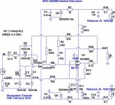
Simplified LM3886 nested gainclone
Ok, here's a simplified schematic with the LM3886. The component values should be regarded as placeholders which are subject to modification after prototyping - it should work stably with the values shown, but may require changes to improve audible sonics.
If a PCB is being attempted, I'd suggest the (previous) complete version with 2 x LM3886 instead, and the 2nd-order compensation schema with the Jung-type GNFB network, etc. Components can be omitted or bridged on the complete version to get the simplified version posted below.
Edit: Some implementation notes - match R6 and R10 to within 0.1% with a DMM; likewise R20 with R13. The actual values are not critical, only the matching. R9 can be implemented as 2 x 1 ohm/2 watts metal-oxide resistor in parallel. Leave enough place to experiment with different input caps for C1 - I'd recommend Siemens MKL or Wima MKP here, but numerous other choices are possible. The electrolytics for the LM3886 can be reduced to 220 or 330 uF per channel as per current gainclone practice, although I tend to use 680 uF or higher. C6 should be polystyrene or silver-mica. C2 should be silver-mica, polystyrene or 1kV ceramic. All the rest can be standard LM3886 gainclone practice.
(Sorry about the legibility of some of the text - I had to export it as .wmf from LTSpice on Wine on Linux, convert the .wmf to .jpg in GIMP, etc.)
Attachments
Last edited:
The electrolytics for the LM3886 can be reduced to 220 or 330 uF per channel as per current gainclone practice, although I tend to use 680 uF or higher.
I'm probably missing them on the drawing, but which electrolytics are you talking about? The 1000uF Rubycons?
Yup, I used the specs of the 1000 uF/35 V Rubycon ZL in the earlier LM1875 simulation schematics, mainly because they're low ESR, have excellent sonics, and are widely available. It should work ok with the LM3886, although the recommended values for supply bypass caps are lower.
Question:
When C9, C10 are 220uF//220uF, then, in that case, can R16, R17 (PI filter) be located upon the power supply board, which makes the power circuit for LM3886 look like this so that LM3886 can run cool enough to drive a 4 ohm speaker from a single chip:
AC
Transformer
Rectifier
2200uF per rail
0.1R per rail (R16, R17)
--optional power supply interconnect--
10,000uF per rail (or 5x 2200uF per rail)
100uF polyester cap per rail
3.3uF (or 4.7uF) high esr polyester cap V+ to V-
Star Ground, Speaker Ground, 0V
Cable (not long)
amp board
220uF//220uF per rail
100nF ceramic or polypropylene cap per rail
lm3886
4 ohm speaker (or 16 ohm speaker or 8 ohm speaker)
This works in practice to get more than enough thermal margin for TDA7294 and LM3886 to run 4 ohm speaker per each chip. Cleaner power makes for cooler heatsink--no extraneous heating like the 47 labs style amps.
Any suggestion for improvements would be quite welcome; but the question is about the location of R16, R17.
Is it correct?
Last edited:
I've been following this with interest as I've had interest in trying this nested topology. However, stabilizing nested amps (SO MUCH open-loop gain) is very difficult, more than your simulations would indicate.
Also, how do you know that you are correctly modeling the power amp chip? I have yet to find a National-provided model. I have seen one or two via this web site, but they were created based on the simplified schematic provided by National. For my use I have tried to take a generic op-amp 'component' in SPICE (Tina-TI) and modify the gain/bandwidth parms based on extrapolation from the National datasheet plots. In any event, I don't think any of these are necessarily close to reality. Google did provide me a 'hit' to a company that seems to make and sell models, but I don't want to pay what they will probably charge.
Interestingly, Twisted Pear Audio sells an amp kit using a nested topology. I need to simulate that to get some clues as to how it might work.
Summary: I don't see anything that says that this thread is anything more than a thought/simulation exercise that won't work in practice. I wish it were not so, and would appreciate any comments from people who have actually built such nested power amps.
P.S., I have much experience in using such a nested topology in production test setups for IC op-amps, so an vouch for the difficulty of getting things to go right.
Question:
When C9, C10 are 220uF//220uF, then, in that case, can R16, R17 (PI filter) be located upon the power supply board
AC
Transformer
Rectifier
2200uF per rail
0.1R per rail (R16, R17)
...
Any suggestion for improvements would be quite welcome; but the question is about the location of R16, R17.
Is it correct?
Yes, no problem. R16 & R17 are optional - they help a bit in quieting the 50 Hz harmonics from the rectifiers. They can be placed on the PSU board. For the rectifiers, you can consider using fast, soft recovery rectifiers like the BYV32-200 or similar. I've used them previously in a discrete amp, and they're noticeably quieter - the background 50 Hz harmonic hash is distinctly muted, even without the use of snubber capacitors.
However, stabilizing nested amps (SO MUCH open-loop gain) is very difficult, more than your simulations would indicate.
Agreed - it took a while to figure out a reliable way to stabilize a nested gainclone while still retaining favourable sonics, and it's still work in progress. The best bet is either the Jung or the nested Howland Current Pump (a la Penasa). The nested Howland will probably win on stability.
Interestingly, Twisted Pear Audio sells an amp kit using a nested topology. I need to simulate that to get some clues as to how it might work.
That's probably the MyRef Rev A or Rev C by Mauro Penasa. It's a transconductance stage (Howland Current Pump) wrapped within a traditional Voltage-Series feedback outer loop. The tricky thing there is the compensation for the LM318 front-end op-amp - Rev A and Rev C use different schemas, and are audibly different.
Summary: I don't see anything that says that this thread is anything more than a thought/simulation exercise that won't work in practice.
No better way to prove or disprove it, other than by prototyping and validating it. I'm fully confident about the stability of the 20W LM1875/NE5532 nested gainclone, but less so about the LM3886/NE5532 one. However, there's no harm in building a few prototypes and bringing them up at lower rails like +/- 24V. The worst that can happen is that some magic smoke may escape from the chipamp, but it still has SPiKe protection. We'll see...
. . .No better way to prove or disprove it, other than by prototyping and validating it. I'm fully confident about the stability of the 20W LM1875/NE5532 nested gainclone, but less so about the LM3886/NE5532 one. However, there's no harm in building a few prototypes and bringing them up at lower rails like +/- 24V. The worst that can happen is that some magic smoke may escape from the chipamp, but it still has SPiKe protection. We'll see...
I have today ordered Philips NE5532's,
and also JRC4580 (M-audio audiophile 192 sound card) and 4560 (big current SIP size) for other projects,
and also the 15v zenier diodes.
It will take a week for arrival.
Currently on hand are NE5534's, JRC4556 (Audigy 2), and TL061 (jfet), along with 12v zenier diodes. So, if these won't do, then I'll just wait on the mailbox for the new parts to arrive.
Stability
In replacing LM1875 with LM3886, we have replaced a more-stable power op-amp with a less-stable power op-amp.
Unfortunately, LM3886 is inherently less-stable.
Inverting mode can help it somewhat, according to both empirical data and working examples of common usage that demonstrate inverting LM3886's working with out-of-spec gain settings.
This all the data I have on the LM3886 stability errata.
. . . The best bet is either the Jung or the nested Howland Current Pump (a la Penasa). The nested Howland will probably win on stability.. . .
In replacing LM1875 with LM3886, we have replaced a more-stable power op-amp with a less-stable power op-amp.
Unfortunately, LM3886 is inherently less-stable.
Inverting mode can help it somewhat, according to both empirical data and working examples of common usage that demonstrate inverting LM3886's working with out-of-spec gain settings.
This all the data I have on the LM3886 stability errata.
If the LM3886 Howland Current Pump is used in inverting mode, then there are two alternatives for the NE5532:
i) Make the NE5532 inverting, with non-inverting voltage-series GNFB (a la Mauro Penasa MyRef); or
ii) Make the NE5532 non-inverting, with inverting voltage-shunt GNFB.
Both are feasible, but at the expense of more complicated compensation schemas, IMHO. I'll try them out if the present non-inverting topology doesn't stabilize easily or turns out to be audibly inferior.
I haven't simulated it, but the JRC4556 should be usable in this application - it isn't terribly fast, which is an advantage here (for stability). No idea about the sonics.
Some historical data on that:
JRC4556, JRC4558 are frequently removed, discarded and replaced.
JRC4560, JRC4580 are in some of the favored sources and devices here at diyaudio.com.
These are simple facts, correlation is unlikely, and these facts might not apply. However, after consideration, I'd prefer to await the arrival of the NE5532 that is specific for this project.
My apologies! NE5532 has not yet arrived.
The reputable JRC NJM4560 did arrive and I could employ them if you think they are compatible with this project.
Opinion: So many people enjoy these that it seems a fun idea to make LM3886 "sound like" a really big NJM4560 by using nested topology.
However, I could certainly await the arrival of the NE5532's if that's the best option for success.
- Status
- This old topic is closed. If you want to reopen this topic, contact a moderator using the "Report Post" button.
- Home
- Amplifiers
- Chip Amps
- LM1875 nested Gainclone