Hi !!
I bought two 3886 to drive four 20W 4Ohms speakers, two for each channel, so, 8Ohms, 40W.
Each 3886 will work with 84 V, and they will be fixed in a BIG heatsink. I'll use HIGH PASS filter to this !
Now, I want to know, before build this, if anyone have some tips and tricks about this 3886 !")
Thanksss !!!!!!!
I bought two 3886 to drive four 20W 4Ohms speakers, two for each channel, so, 8Ohms, 40W.
Each 3886 will work with 84 V, and they will be fixed in a BIG heatsink. I'll use HIGH PASS filter to this !
Now, I want to know, before build this, if anyone have some tips and tricks about this 3886 !
Thanksss !!!!!!!
Wow 
But I"m thinking in use 50v 47uF capacitors between the amp and the speakers. These amps (3886) and speakers are not going to play bass, just mids and high... Bass will be an c200 with 12" 125W subwoofer.
With these capacitors connected between the amp and speakers, will the speakers go away if the supply connection fail?
If the answer is yes or no, doesn't matter, this is not gonna fail
Any crossovers project ?
the LM3886 is an opamp so (within limits -- it is a high gain, high power device) you can tailor the feedback network to provide the slope you need -- you must use a RC snubber on the output if you are going to use it as an active filter.
you can use Texas Instruments Filter-Pro (freeware) to calculate the filter values -- plug in a gain of 20.
you might be better off just using an opamp buffer, however -- one with a fairly high gain bandwidth product --
you can use Texas Instruments Filter-Pro (freeware) to calculate the filter values -- plug in a gain of 20.
you might be better off just using an opamp buffer, however -- one with a fairly high gain bandwidth product --
It has been a while that I was playing with chip amps but as far as I remember your voltage is too high. When you say 84V - is that between rails, or + 84V and - 84V.
Even between rails is too much, and other combination is leathal.
I would suggest lower voltage - something like 31 - 32 V per rail. max.
Even between rails is too much, and other combination is leathal.
I would suggest lower voltage - something like 31 - 32 V per rail. max.
-_nando-_ said:But I"m thinking in use 50v 47uF capacitors between the amp and the speakers. These amps (3886) and speakers are not going to play bass, just mids and high... Bass will be an c200 with 12" 125W subwoofer.
With these capacitors connected between the amp and speakers, will the speakers go away if the supply connection fail?
With polar cap, I guess it depends on which side of the rails that fail. I have tried many exotic output caps on the output, and they affect the sound quality. Worse to be precise. But my Nippon-Chemicons is okay. It seems that old (burned-in) caps work better
how long has the 3886 been made? much longer than any cpu. they probably have made new chips on different process, and still keep old PDF for everyone.
i wouldnt be suprised if you could run 50v a rail and no trouble at all as long as it doesnt oscllate.
they are cheap, very mature and probably with a HUGE margin of error.
i wouldnt be suprised if you could run 50v a rail and no trouble at all as long as it doesnt oscllate.
they are cheap, very mature and probably with a HUGE margin of error.
-_nando-_ said:84v total, it's 42+42v.
I don't have other transformer, and I'll cut the low frequency, so I don't think the 3886 will stress so much heh !
If your transformer is 42 + 42 V, after unregulated PS (diodes and caps) you will have roughly 58 V +58 V. Please read National spec sheet because you will burn your chip. Your Voltage is exceding maximum allowed for the chip. You will have 116 - 119 V between rails.
http://www.national.com/pf/LM/LM3886.html
-_nando-_ said:I found LM 338 to regulate this 42v to 30v.... But I need the negative voltage equivalent (like LM78XX / 79XX) to regulate -42 to -30v....
What's the part number please?
Pedja Rogic regulated Gainclone supply - LM388
You should use two LM388 to get +-30 VDC.
This supply is very wellknown at this forum.
If you search "Pedja LM388"
you will find several threads on how using LM388 for gainclone.
You need trafo with two separate windings.
Such a trafo has 4 wires on secondary.
Not a trafo with one winding with 0V tap at half/middle (3 wires).
Hello nando,
If you already have a centre tap transformer. Better option i think will be to use the normal 78xx and 79xx with a power transistor 3055, 2955. To achieve the required voltage eg 30v (assuming you have only 7824) you can lift the groung of 7824 to +6v by a 7806. Likewise for the negative voltage. The output of the regulator is connected to the base of transistor, collector to unregulated supply(42v) and emitter as output. Not sure if there is some other problem in using this. But i have being using this circuit for quiet some time.
Venki.

venki said:Hello nando,
If you already have a centre tap transformer. Better option i think will be to use the normal 78xx and 79xx with a power transistor 3055, 2955. To achieve the required voltage eg 30v (assuming you have only 7824) you can lift the groung of 7824 to +6v by a 7806. Likewise for the negative voltage. The output of the regulator is connected to the base of transistor, collector to unregulated supply(42v) and emitter as output. Not sure if there is some other problem in using this. But i have being using this circuit for quiet some time.
Venki.
GREAT ideia !
But power transistors have a little loss, like ~0,6v... If I play music loud, will the transistor have more loss?
Mick_F said:Consult the datasheet! If you want to drive 4 Ohm speakers, your rail voltage should not exceed 30 V
Mick
So ! I'll drive an 8 Ohm 40W speaker !
In the datasheet says that the MAX voltage is 94v (47+47), when there's NO SIGNAL in... So, this is the peak voltage when the PSU is not heavy loaded, like when we play music loud. My PSU give 84v (42+42) when it's not loaded ! So, playing music this voltage will fall down. The same PSU is shared with an c200 driving a 4 Ohm 125W subwoofer, so when I push it to LOUD the voltage of supply will realy fall, then the 3886 will not suffer so much. The heatsink is big too !
With all this, still dangerous use 3886's this way ? Will be two 3886's and a c200 in the same supply... It will be used every day, but not too loud

-_nando-_ said:Wow
But I"m thinking in use 50v 47uF capacitors between the amp and the speakers. These amps (3886) and speakers are not going to play bass, just mids and high... Bass will be an c200 with 12" 125W subwoofer.
With these capacitors connected between the amp and speakers, will the speakers go away if the supply connection fail?
If the answer is yes or no, doesn't matter, this is not gonna fail
Any crossovers project ?
47uf and 8ohm(two 4ohm series connected) = 400hz crossover frequency. This is too high for crossing over to a sub.
For sure, I tested and I hated the sound.
But, I'll not use crossover for 3886's anymore, I'll use a 7way equalizer, then I reduce the bass.
I'll just use a crossover for SUB, but I want cut the frequency about 150Hz, and I can't find any crossover over the internet with this frequency cut...
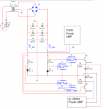
About the SUPPLY, I think I found the solution, designing the attached supply.
The logical is the following:
+- 30VAC -> Retification -> +- 42VDC --> Fuse* --> Zenner 24v Regulator** -- LM7812 and LM7912 regulators*** --> 7824 and 7924 regulators **** --> TIP3055 and 2955 power transistors
* After the fuse, the C200 Amplifier will be connected.
** I'll use zener 24v regulator, because 78/9XX only suports max 35v
*** It's to lift the ground of the 7924 and 7824 regulators, because they only suports 40v. So they will work with + - 30V
**** They will drive the power transistors, because of the current that the system will drain
The output voltage to LM3886s will be +-35v, not 36, because the power transistors are not 100% efficient.
35v is a very good voltage, they will drive 8 Ohms speakers.
What you think?
FEEDBACK WELCOME !
edit: I used Multsim7 only to DRAW the schematic... I don't know use this software enough to simulate and etc... I used paint too heh
But, I'll not use crossover for 3886's anymore, I'll use a 7way equalizer, then I reduce the bass.
I'll just use a crossover for SUB, but I want cut the frequency about 150Hz, and I can't find any crossover over the internet with this frequency cut...
About the SUPPLY, I think I found the solution, designing the attached supply.
The logical is the following:
+- 30VAC -> Retification -> +- 42VDC --> Fuse* --> Zenner 24v Regulator** -- LM7812 and LM7912 regulators*** --> 7824 and 7924 regulators **** --> TIP3055 and 2955 power transistors
* After the fuse, the C200 Amplifier will be connected.
** I'll use zener 24v regulator, because 78/9XX only suports max 35v
*** It's to lift the ground of the 7924 and 7824 regulators, because they only suports 40v. So they will work with + - 30V
**** They will drive the power transistors, because of the current that the system will drain
The output voltage to LM3886s will be +-35v, not 36, because the power transistors are not 100% efficient.
35v is a very good voltage, they will drive 8 Ohms speakers.
What you think?
FEEDBACK WELCOME !
edit: I used Multsim7 only to DRAW the schematic... I don't know use this software enough to simulate and etc... I used paint too heh
Attachments
- Status
- This old topic is closed. If you want to reopen this topic, contact a moderator using the "Report Post" button.
- Home
- Amplifiers
- Chip Amps
- LM 3886 Tips...