Hi,
tweaks to Your last circuit from #15:
Increase L1 (choose in LT-spice: Würth No.742 793 2, 0.52µH 6A)
Add two caps after L1 to gnd.
1st a 100µF (eg. Nichicon UPG1V101MPH) no low-ESR, ESR may be as high as 1Ohm to prevent ringing of the LC-circuit.
2nd a small ultralow-ESR Ceramic to clean up the MHz-range (eg. TDK 1µF, X7R, C3216X7RIE105M)
Interchange Gyrator and Reg position, hence let the Reg follow the LC-circuit. This gives better HF-noise reduction.
Change the voltage setting resistors R3/R4 from 100/860Ohms to 100/1k24 to increase the Reg´s output voltage to ~16-17V. C2 may be a small 1µF ceramic cap.
Add a second LC-circuit at the output of the Reg like the first one, ecept that the 1st Cap be a 100µF low-ESR (eg. Nichicon UPL1V101MPH).
Now let the Gyrator-circuit follow.
Increase the Base-resistor-network R1/R5 values from 1k/6k5 to 10k/68k.
Change C1 to the 2-Cap 100µF/1µF low ESR-combination. The increase in R1 and the caps values lowers the breakpoint frequency and improves regulation.
Add another 2-Cap low-ESR cap combination to the output of the gyrator.
jauu
Calvin
I was able to eventually nail the switching spike with a traditional inductor (instead of a ferrite bead). ") Same inductance, 10uH, just a torroidal wound coil of the type I see on the input of so many power supplies these days it seems:
Same inductance, 10uH, just a torroidal wound coil of the type I see on the input of so many power supplies these days it seems:
Digi-Key - M8802-ND (Manufacturer - 2101-H-RC)
AndrewT: sure enough, after my last post I discovered the ESP page from way back when on cap multipliers. He goes into using that second order filter for the cap multiplier:
Capacitance Multiplier Power Supply Filter
I agree - for just the cost of another resistor and small cap that does sound like a good idea. I've added it here.
Calvin: Some good thoughts! I'll leave it up to another poster to try some of those arrangements of the parts since this circuit is as far as I'm going with it for now.
wwenze: thanks for the ferrite bead pictures. I've decided I don't know enough about beads right now to try them for this app though. In the past I've always thought of beads as something for removing really high frequency noise, like 100mHz+. I think I'm too out of date on the new stuff here. I'll have to stick with coils. Hopefully Calvin or someone else with experience will post some sim results or scope shots with beads. Would be interesting to learn.
Some changes:
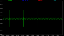
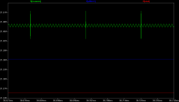
* The switching spike is now an order of magnitude faster, hence nastier, and the amplitude is tripled. I had a mistake in the v source specs before and the spike was not symmetrical (as I had intended).
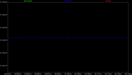
* A small resistance is added to a voltage source as a first pass at non-idealizing it, and providing some more "R" for the following R-L/R-C(cap mult) filter.
* A series resistor R6 is added to add R/C filtering to the L/C filter. It could be removed with likely little effect, but if so the real world resistance of that inductor should be added to its model specs.
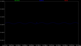
* The inductor forms an L-C filter, of course, with the cap multiplier being the "C". Since the actual lap top brick will probably (?) have an output capacitor, that would produce a C-L/R-C filter in total. I've left an input capacitor out since it wouldn't seem to make much sense when fed by a (nearly ideal) voltage source model for the sim.
* C3 and C4 are stability caps that Linear Tech says must be there (especially C4), as a minimum, to keep the LT1083 from oscillating since it is an LDO. Not clear to me yet if the cap multiplier, looking back into its output, would effectively work to replace C3 or if it is still needed.
* D1 is the standard protection diode Linear recommends to prevent damage in case of a large output cap with the reg input shorted or low R.
* Large voltages specified for the tantalum caps to reduce the chance of their going *poof* and burning.
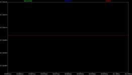
* 16Vdc out now, rather than 18Vdc, as essentially nearly the highest regulated output voltage possible given that R6, the coil, and the voltage source R all now drop some additional voltage.
* A rough efficiency calculation gives around 72% with everything shown.
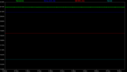
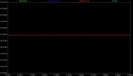
So unless there is a big mess-up in my simulation model - which there probably is! - here are the conclusions I see when using this circuit after a laptop SMPS brick:
* If the goal is to eliminate the switching spike, the inductor alone may do the job.
* If the goal is to reduce the more sinusoidal nose, like that 1Mhz background harmonic, the cap multiplier and R6 are probably a good idea.
* And if the goal is tight regulation, slap on the regulator.
Same inductance, 10uH, just a torroidal wound coil of the type I see on the input of so many power supplies these days it seems:Digi-Key - M8802-ND (Manufacturer - 2101-H-RC)
AndrewT: sure enough, after my last post I discovered the ESP page from way back when on cap multipliers. He goes into using that second order filter for the cap multiplier:
Capacitance Multiplier Power Supply Filter
I agree - for just the cost of another resistor and small cap that does sound like a good idea. I've added it here.
Calvin: Some good thoughts! I'll leave it up to another poster to try some of those arrangements of the parts since this circuit is as far as I'm going with it for now.
wwenze: thanks for the ferrite bead pictures. I've decided I don't know enough about beads right now to try them for this app though. In the past I've always thought of beads as something for removing really high frequency noise, like 100mHz+. I think I'm too out of date on the new stuff here.
I'll have to stick with coils. Hopefully Calvin or someone else with experience will post some sim results or scope shots with beads. Would be interesting to learn.Some changes:
* The switching spike is now an order of magnitude faster, hence nastier, and the amplitude is tripled. I had a mistake in the v source specs before and the spike was not symmetrical (as I had intended).
* A small resistance is added to a voltage source as a first pass at non-idealizing it, and providing some more "R" for the following R-L/R-C(cap mult) filter.
* A series resistor R6 is added to add R/C filtering to the L/C filter. It could be removed with likely little effect, but if so the real world resistance of that inductor should be added to its model specs.
* The inductor forms an L-C filter, of course, with the cap multiplier being the "C". Since the actual lap top brick will probably (?) have an output capacitor, that would produce a C-L/R-C filter in total. I've left an input capacitor out since it wouldn't seem to make much sense when fed by a (nearly ideal) voltage source model for the sim.
* C3 and C4 are stability caps that Linear Tech says must be there (especially C4), as a minimum, to keep the LT1083 from oscillating since it is an LDO. Not clear to me yet if the cap multiplier, looking back into its output, would effectively work to replace C3 or if it is still needed.
* D1 is the standard protection diode Linear recommends to prevent damage in case of a large output cap with the reg input shorted or low R.
* Large voltages specified for the tantalum caps to reduce the chance of their going *poof* and burning.
* 16Vdc out now, rather than 18Vdc, as essentially nearly the highest regulated output voltage possible given that R6, the coil, and the voltage source R all now drop some additional voltage.
* A rough efficiency calculation gives around 72% with everything shown.
So unless there is a big mess-up in my simulation model - which there probably is!
- here are the conclusions I see when using this circuit after a laptop SMPS brick:* If the goal is to eliminate the switching spike, the inductor alone may do the job.
* If the goal is to reduce the more sinusoidal nose, like that 1Mhz background harmonic, the cap multiplier and R6 are probably a good idea.
* And if the goal is tight regulation, slap on the regulator.
Attachments
-
 CapMult + Inductor + LT1083_4 4 voltages.png6.7 KB · Views: 395
 -
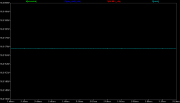
 CapMult + Inductor + LT1083_4 Vsource.png7.6 KB · Views: 363
 -
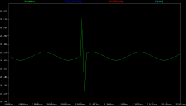 CapMult + Inductor + LT1083_4 Vsource_single.png8 KB · Views: 373
 -
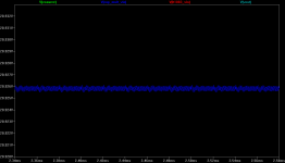 CapMult + Inductor + LT1083_4 CapMultVin.png8.9 KB · Views: 370
 -
 CapMult + Inductor + LT1083_4 LT1083Vin.png7.6 KB · Views: 371
 -
 CapMult + Inductor + LT1083_4 Vout.png6.9 KB · Views: 108
 -
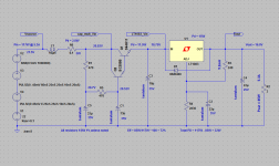 CapMult + Inductor + LT1083_4 circuit.png35.1 KB · Views: 226
Last edited:
I would call that a success.
Now breadboard it and stick a scope on the three test points to see if those good results come out in practice.
I have not used it yet but some are suggesting attaching a series cap to your headphone lead and using AC detection of the headphones to listen to the noise at the output. Apparently quite revealing.
AndrewT: I agree - time to breadboard it and see if reality matches up with the sim at all. I think I will. I have all the parts lying around except the coils, but I've been accumulating a Digikey order. Trying that AC test with the headphones would be interesting.
I found one mistake that I made. I had intended to keep the corner frequency the same going from first to second order rc, but it hit me I need to make the filter parts values asymmetric to do it. Looks like changing C5 to 150uf would do the job, from this calc:
2nd order CR filter Design tools
Nothing special about that particular Fc though, just the one mentioned in the article.
I think I will. I have all the parts lying around except the coils, but I've been accumulating a Digikey order. Trying that AC test with the headphones would be interesting.I found one mistake that I made. I had intended to keep the corner frequency the same going from first to second order rc, but it hit me I need to make the filter parts values asymmetric to do it. Looks like changing C5 to 150uf would do the job, from this calc:
2nd order CR filter Design tools
Nothing special about that particular Fc though, just the one mentioned in the article.
Last edited:
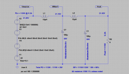
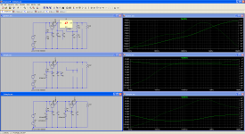
Just a LCLC filter does the job...
Messing with the circuit a bit more, it looks like a simple 2 stage LC filter might do a better job with the expected high frequency stuff from a laptop brick SMPS than a single inductor plus the cap multiplier.
The single inductor gets rid of most of a switching frequency transient, but not all, and the tiny amount left goes right through the cap multiplier and regulator it seems.
But the second LC stage seems to nail everything down to any voltage level that would matter. A side benefit is high efficiency - the only loss is that resistive component of the inductor impedance, which is tiny of course. Probably around 98% efficient. Then bolt a linear regulator on as needed for lower voltages.
Attachments
For 5A of output the 150uF is too small.
What is the ripple current through the first 150uF? What is it's ripple rating?
What is the resistance of the 10uH inductors. Add that resistance into your simulator.
Add some esr and esl to your "perfect capacitors". This will allow your simulator to model some the real happenings in your circuit.
What is the ripple current through the first 150uF? What is it's ripple rating?
What is the resistance of the 10uH inductors. Add that resistance into your simulator.
Add some esr and esl to your "perfect capacitors". This will allow your simulator to model some the real happenings in your circuit.
What is the resistance of the 10uH inductors. Add that resistance into your simulator.
All inductors have a SRF - Self Resonant Frequency. This is where they resonate with their shunt capacitance, giving a very high impedance. Beyond that frequency the shunt capacitance dominates. For accurate simulation you'll need to shunt each inductor with that stray capacitance - it'll mean your spikes won't disappear so well.
Thanks for the timely reminder.
Here's a Google Link to a pdf that is useful.http://www.google.co.uk/url?sa=t&so...sg=AFQjCNFWsroIibSzTdPJZvCcfpxbqNW7aw&cad=rja
Here's a Google Link to a pdf that is useful.http://www.google.co.uk/url?sa=t&so...sg=AFQjCNFWsroIibSzTdPJZvCcfpxbqNW7aw&cad=rja
lol - I hadn't had a chance to circle back to this thread in a while. I wound up ordering the coils from Mouser:
2303-V-RC Bourns Power Inductors
which arrived yesterday, and sure enough, using a Sony laptop 19.5V 4.5A brick loaded down to 3A the switching transients still largely go right straight through.
2303-V-RC Bourns Power Inductors
which arrived yesterday, and sure enough, using a Sony laptop 19.5V 4.5A brick loaded down to 3A the switching transients still largely go right straight through.
Last edited:
Pardon me for not replying in this thread for quite a while.
Capacitors using models in LTspice.
I guess if there is no need to remove low frequency hum, don't use that IC linear regulator?
(Just checking - can small-signal analysis be used to check the PSRR in this case?)
Capacitors using models in LTspice.
I guess if there is no need to remove low frequency hum, don't use that IC linear regulator?
(Just checking - can small-signal analysis be used to check the PSRR in this case?)
Attachments
Last edited:
Hi,
Yes, if there´s not much to worry in the LF-range than the gyrator is sufficient to clean the HF-range.
jauu
Calvin
see what Ypu´ve been told in #14??the switching transients still largely go right straight through.
Yes, if there´s not much to worry in the LF-range than the gyrator is sufficient to clean the HF-range.
jauu
Calvin
- Status
- This old topic is closed. If you want to reopen this topic, contact a moderator using the "Report Post" button.
- Home
- Amplifiers
- Power Supplies
- Linear post regulator for SMPS, what's your take?