I have a guitar amp with a Lin topology power amp in it. The push-pull AB-class current drivers are made from TIP31C/32Cs Darlingtoned with MJ15001/002s. I can't find a good source for them, so I am looking at TIP41C/42Cs and 15003/004s as replacements. I believe from several things I have seen that these should be plug-n-play replacements, and I don't think I'll have to re-bias anything. According to the data sheets, the differences are that h(FE) is a bit higher, V(CE)sat is also a little higher-- but since they're biased fairly strongly into the active region, this shouldn't matter-- and V(BE)on is a little higher, which should somewhat offset the current gain difference. I'll be checking to make sure that they're into the active region, and the amp has a current limiter stage just before the push-pull stage. Has anyone had experience with doing something like this and could give me an idea if it will work OK?
I am also going to add a fan as well as some vent holes (I plan to drill vents in the bottom of the chassis and have the fan blow out- this will draw cool air across the power transistors and heat sink). This is where the problem came from in the first place- I played it too loud on a hot day and one of the drivers went intermittent on me. Does anyone know of anything that might help cool the amp more?
The amp has always been a little noisy, and it's definitely the power amp, not the preamp- I have switched jacks and I've tried it with shorting plugs to short the input. Breaking it open I found that the power supply is just a center-tap transformer at 2:1, a bridge rectifier across the ends of the secondary, and a pair of 6800uF caps, and that's it. I am planning to put a regulator on it; there is sufficient voltage to add a pair of diodes to the center tap and use two positive regulators, and I am getting a pair of LM338s with all the trimmings; I have a thread running asking for technical advice on the Power Supplies forum, but I think I've figured it all out, unless someone comes up with some last-minute problem. However, the designers have done some rather peculiar things with ground:
1. The speaker jacks are connected to a network with a pair of 0.68 ohm 10W resistors in parallel to ground, and a "T" with 220 and 22 ohm resistors on the arms and a 0.022uF cap and 10 ohm resistor in parallel to ground; the 22 ohm arm of the "T" goes to the 0.68 ohm resistors. This seems rather odd to me, and I suspect there might be some noise from a ground float as a result, but I also suspect that those 0.68 ohm resistors are a last-ditch effort to handle a shorted output. Does anyone know if this is a good conjecture on my part, and if this arrangement is likely to cause noise?
2. The heat sink is completely insulated from the transistors, but instead of tying it to ground directly, the designers have used a 0.1uF cap. I suspect that this was not a real great idea, and I intend to replace the cap with a jumper. Does anyone know of a reason why they would do this, and whether this could also be a source of noise?
3. I'm looking at the board, and there are- hold on to your hat- three grounds. The one tied into the center tap of the transformer goes to a lug that ties to the chassis, so that's normal- but then it goes out and gets split into two traces (yes, kids, I have two ground traces running side-by-side all the way across the amp board to the connector that goes to the preamp, and yes, both of them go to that connector, and then (and ONLY then) one of them connects to the main power amp ground). After being routed to the far side of the board, "ground" (whatever the heck "ground" means when there are three of them) then goes cruising back across the middle of the board to act as the actual ground that the amplifier uses for all its bypass caps and so forth- and all the way back where it came from, the same freakin trace goes past the place where the original split occurred, and there they are: three "ground" traces running right next to each other. And to top it all off, the schematic has one of the grounds labeled as "dirty ground." GAH!!!. Now it's my experience that ground problems are BAD in audio equipment, and this looks to me like the ground loop from the heart of evil. My tendency is to star ground everything- just go nuts with lugs and heavy-gauge wire. Does anyone know anything about why any sane individual would make a design with multiple different grounds when there isn't any indication that any of them are actually electrically isolated from one another? What am I missing here? Is this voodoo, or is there an actual design concern that I need to learn about here???
Thanks in advance for any help anyone can provide on these questions. If someone needs to see the schematic, I'll try to do an attachment- we'll see if it's actually readable at less than 1000 pixels across.
1. The speaker jacks are connected to a network with a pair of 0.68 ohm 10W resistors in parallel to ground, and a "T" with 220 and 22 ohm resistors on the arms and a 0.022uF cap and 10 ohm resistor in parallel to ground; the 22 ohm arm of the "T" goes to the 0.68 ohm resistors. This seems rather odd to me, and I suspect there might be some noise from a ground float as a result, but I also suspect that those 0.68 ohm resistors are a last-ditch effort to handle a shorted output. Does anyone know if this is a good conjecture on my part, and if this arrangement is likely to cause noise?
These 0.68R resistors are speaker current sensors, so that feedback is partially voltage sense and current sense. This gives the whole amp higher than hi-fi standard output imedenace and lets speaker to resonate at some 75-85Hz.
Proper grounding seems very hard to me here...
OK. I assume I'm pushing the V(CE) in the current driver just far enough up into the active region to ensure linear operation, for the one of the four transistors that is the lowest, right? That should be V(CE) just barely above V(CE)sat(max) from the data sheets for the one of the four of Q8-Q11 that has the lowest V(CE) with relation to its particular V(CE)sat(max), if I understand the operation of the amp correctly; that will give the maximum possible loadline for all four transistors, and output will then be limited by the least of, current available from the supply, top of the lowest loadline.jaycee said:The transistors you mention will be suitable for replacement, however you will have to rebias the amp.
The bit you labelled "Current Mirror" Q5, is actually the bias circuit.
I believe that I should be starting with the pot AP-1 at minimum resistance, which should give minimum current through Q4, and slowly crank the resistance up, checking the V(CE) on Q8-Q11, and watching the current thru Q4 to make sure it doesn't get too high; if it does, then I'll have to consider changing the value of R16 to a higher value, I'll start with 750. If, on the other hand, I can't get the current high enough, then I'll have to move the bias point of Q5 up a little bit by reducing R14 and/or increasing R13, as long as this doesn't push Q4's current too high.
Once I have the correct minimum V(CE) for Q8-Q11, then I want to check the quiescent position of Q4 on its loadline and make sure it's as close as practical to the center of the loadline. If not, adjust R16, R17, and finally R13/R14, and as a final position consider adding a resistor to the collector of Q5 to mirror R17.
Do I have that right?
Yes, proper grounding seems pretty dicey to me too. My question on this is, do I need to worry about it as a potential noise source, and if so will regulating the power supply help? And is there anything that I might do to it to improve matters without compromising the protection circuit, if it's not enough just to regulate the power?jaycee [/i][B]Some of the noise might well be the zener diode in the current source feeding the diff amp pair. [/B][/QUOTE]Ahhh-HA! Yes said:These 0.68R resistors are speaker current sensors, so that feedback is partially voltage sense and current sense. This gives the whole amp higher than hi-fi standard output imedenace and lets speaker to resonate at some 75-85Hz.
Proper grounding seems very hard to me here...
Regarding the resonance, remembering this is a guitar amp, 75-85Hz is around the open low E string (82.407Hz at concert pitch), making the bass strings on the axe sing nicely. Experience with the amp confirms this; E thru G are quite strong on this amp, with all my axes. G# starts to fade a bit, and A is less strong. 110Hz is, of course, the A string.
Regarding the higher output impedance, again, this is a guitar amp, so it has to handle anywhere from a 4-ohm to a 16-ohm load (one speaker, two speakers in parallel, four speakers in series-parallel, or two speakers in series; or potentially, 16-ohm impedance speakers, which is not uncommon for guitar amp speakers, although it is almost never seen in the hifi world); bear in mind as well that I am running this amp with the two internal speakers in parallel, for a 4-ohm load on the left channel, and with a 2-12 parallel cabinet on the right channel, which is also a 4-ohm load. That might affect the recommendations you give, and if so, I'd be interested to hear about it.
Thank you both for your advice; it is most valuable to me.
I am not sure you took my comment.
I was not talking about load impedance handling, but series source impedance, i.e. very low load damping. While it is recomended to have high damping for hi-fi (damping factor of 30 and more up to thounsends), guitar amps let cone undamped, because resonace is believed helpful.
this might be helpful, although Rod does not say much about grounding in low damping topologies.
best regards
Adam
Ahhh, I see, yes, you are right, I did misunderstand you. Yes, in fact, resonance is very important to the sound of a guitar amplifier. If you listen to Carlos Santana on his early albums, playing with a hollow-body guitar and a compander, and getting resonances (limited feedback) during his leads, you'll understand precisely why. The upshot of this is I probably need to not fool with it, because it will remove some of the sound I like.darkfenriz said:I am not sure you took my comment.
I was not talking about load impedance handling, but series source impedance, i.e. very low load damping. While it is recomended to have high damping for hi-fi (damping factor of 30 and more up to thounsends), guitar amps let cone undamped, because resonace is believed helpful.
this might be helpful, although Rod does not say much about grounding in low damping topologies.
best regards
Adam
I'll review that article in more detail and analyze the design a bit more, too, so that I comprehend what the designers were trying to accomplish. Perhaps it's not just a matter of safety feedback.
Thanks very much.

Concerning regulation, it's better to regulate only the differential stage supply and perhaps the VAS supply. There's a constant current source at differential but it seems to be highly dominated by the fluctuations in Vee. If you regulate the differential supplies the circuit should become less sensitive to ripple and effects of supply sagging. I guess this is one of the main sources of the noise you are experiencing.
Your explanation of the grounding still remained unclear to me. A picture might be much more visualizing. As far as i know it's quite common to run separate power and signal grounds. If there are digital chips in the circuit they should also use a "separate" ground (which is so full of transient switching currents that it could be considered "dirty"). Maybe this is the case.
Concerning the current sensing circuit; I did some simulations with different feedback methods about a month or two ago and wrote about the results to a thread at ssguitar.com.
http://www.ssguitar.com/index.php?topic=75.msg785#msg785
Reading it might be a good continuation to the Rod Elliott article, just don't get repelled because of talk about output transformers. You have to register to view the attached pictures though.
The current sensing / mixed-mode feedback circuit is a quite common feature of guitar amps probably because it "mimicks the tube amp response". Actually the circuit has nothing to do with mimicking tube circuits, both circuits just tend to response to load impedance similarily. I guess the high current ground path of the circuit should be grounded the same way a speaker load usually is - which is straight to the main star ground point. The low current grounds of it could go to signal ground, or so I guess. Anyway, most of the grounding theory is just speculation since it's highly circuit/PCB design/layout etc. related. You have to test what works best.
Thanks, that was helpful.
The transistors showed up today, and it looks like they were plug-n-play after all. I'm going to do more with it tomorrow, but at this point, it looks like the regulators removed the noise and the adjustments needed for biasing were minimal. I made two modifications besides changing the output transistors and adding the regulators:
1. The heat sink was bypassed to ground with a .1uF cap. I replaced this with a jumper.
2. The ground from the service was attached to the case, but the ground from the amp was not. I attached the ground from the amp to the case where the power enters the Lin amp.
With 100mA of quiescent (shorted input) current at the emitters of the MJ15003/004s, the amp sounds just a bit better than it did with the original MJ15001/002s; the biasing of the Class-A voltage amplifier was not significantly disturbed; it is still within a very small percentage of the center of the load line, in fact it is just slightly better than it was. The power supply regulation project failed, though; I will now buy a toroid with two secondaries and make it work. Anybody wanna buy a used transformer, cheap? Just kidding. It's bench supply meat. I may build some more Lin amps and it would make a pretty good test supply for that.
Direct-coupling the heatsink does seem to have improved the hum slightly, but that may be subjective, and I intend to be picky. I've also observed that there is significant hum in the preamp as well, so it's clear to me that regulated power is mandatory in this application. That was there all along, and of course it doesn't matter for that what I do to the Lin amp. I decided to leave ground alone other than to ground the heatsink; after I get the supply regulated, I'll run an A/B taste test to see whether a capacitor or jumper is more appropriate, I couldn't tell for sure with all the hum from the ripple.
Hey, I tried bypassing the base of the diff amp current source transistor to ground and then to +40V with a 0.1uF cap, and it didn't do a dang thing for me. I thought of increasing the 220uF cap to ground from the +40V rail right next to where the Zener gets its supply, but didn't bother doing anything about it; my expectation is that regulating the power supply will correct the problem if that's it.
Hi Shredly,
is it hum and it's harmonics that's the noise problem or wide band noise (white or pink)?
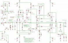
There's a mistake in the schematic;- C16 is shown connected to top end of R28. It should be bottom end of R28 to C16.
Since R28 is 0r33 it may not make a lot of difference.
The protection circuit seems to be a little unusual and I suspect not very efficient, particularly in view of the mishap that caused the overheating.
I note you managed to bias the output stage but your description of the procedure you were planning to follow could have blown up the output stage. The label saying current mirror is actually next to the Vbe multiplier (as poster said). You seem to understand the effect of changing resistor values but for first start up after component changes you should firstly set the multplier to MAXIMUM resistance to MINIMISE the voltage bias across the output stage. Secondly you would be wise to ALWAYS start up a project on test through a mains light bulb to reduce the risk of blow up.
However it worked and you got away with it.
Your Email is off.
is it hum and it's harmonics that's the noise problem or wide band noise (white or pink)?
There's a mistake in the schematic;- C16 is shown connected to top end of R28. It should be bottom end of R28 to C16.
Since R28 is 0r33 it may not make a lot of difference.
The protection circuit seems to be a little unusual and I suspect not very efficient, particularly in view of the mishap that caused the overheating.
I note you managed to bias the output stage but your description of the procedure you were planning to follow could have blown up the output stage. The label saying current mirror is actually next to the Vbe multiplier (as poster said). You seem to understand the effect of changing resistor values but for first start up after component changes you should firstly set the multplier to MAXIMUM resistance to MINIMISE the voltage bias across the output stage. Secondly you would be wise to ALWAYS start up a project on test through a mains light bulb to reduce the risk of blow up.
However it worked and you got away with it.
Your Email is off.
Just to add to Andrew's post, if it's hum it's likely a ground issue.
There is another fatal error in the schematic, that is that the right leg of the LTP is connected not to the same -ve rail as the rest of the circuit, but to the VAS emitter, which is incorrect.
The LTP CCS is also wrongly implemented. Either R4 or D3 will serve no purpose and the Vref generation I suspect with just a quick look is all wrong. It's also bad practice to take out the feed from Vref like that as you open it up to picking up noise etc.
Hi Richie,
my circuit analysis is not too hot but I think the VAS is connected as a folded cascode. It looks similar and the collector resistor ratio looks about right for that topology. R9 voltage drives the base in common emitter (inverting) and R11 voltage drives the emitter in common base (non inverting). Output from VAS is inverted from both sides of the LTP.
The CCS generates a constant voltage across the series pair of R4 and Vbe of Q3. This forces a constant current ([10-0.7]/2.7=3.4mA) through the resistor and C10 tries to hold the constant voltage steady when dynamically loaded.
Hi Andrew. As I said I only quickly looked at the circuit. Now I see that the CCS is OK - what threw me was R8 which would either screw up the CCS totally or (in this case because it's only 22R which I didn't notice before) just cause slightly poorer CCS action.
You could be right about folded cascode, equally it could be a drawing error.
You could be right about folded cascode, equally it could be a drawing error.
Thanks, you two. I appreciate the feedback. I'll double-check the agreement of the schematic with the one I dug up from the archives; I've already checked that drawing against the circuit board, I'll just make sure I didn't screw it up while I was transferring it to my CAD software.
Bear in mind that this is a commercial product, produced in the late 1980s. It's not my design, and the only two changes I made were to replace the output Darlington pairs and to replace a cap that was decoupling the heatsink to ground with a jumper, after ensuring that the heatsink wasn't connected to the transistors.
I found some instructions for biasing a very similar Lin topology amp at AmpsLab; after looking them over and making sure I understood what they were doing, and looking at my schematic, it was clear to me how to proceed, and that was not quite the instructions I posted here. I was actually rather put out by the fact that I never got any response to my request for review of my procedure, and went looking for myself; I wasn't going to wait around forever.
Since hFE was not sufficiently different to introduce a great deal of bias change at the bases, particularly through a Darlington pair (which is one of the advantages of the Darlington pair), I decided to begin by leaving the settings of the two variable resistors alone; because I was careful during disassembly, I was confident they were set where they had come from the factory. What I did was connect to the bases of the transistors, set my meter for sample-n-hold, and flip the power switch on and off quickly. The values looked pretty good. Next I did much the same across the current limiters, and finally across the A-class amplifier (the one that's connected at its collector to the stuff I labeled "Current Mirror." I chose that name, by the way, because it helped make it clear in my mind what it was doing, not necessarily because that terminology was technically correct- I am aware that a real current mirror is at the collectors of a diff amp pair).
Everything looked OK, so I flipped the power on for longer and started checking for overheating with a thermocouple probe. Again, everything looked OK, so I checked the bias by checking the voltage across the resistors between the output MJ15003/04 pair; 100mA was the quiescent current value suggested that should put them up above the knee and into the active region, and their datasheets confirmed this, so that's what I set it for. The adjustment was very slight on the PNP (bottom) side; and far less than a tenth of a turn on the NPN side as well, indicating that in fact the Darlington pairs were functioning correctly and compensating for the hFE and consequent DC Beta differences.
I'll get back to you on the accuracy of the schematics.
Oh, and most important:
1. It's 120Hz hum; I'm not hearing much in the way of harmonics, just straight 120Hz, fairly standard for a bridge rectifier-filter cap setup. The amp is pretty clean, I don't hear much harmonic distortion (unless I add some in ) , and there's very little white or pink noise; I generally run pre-out of this amp to a very nice clean board, so I can put it through some signal processing hardware I use, then feed it back to the power in, and I record off that board as well. There is a fair bit of pink noise from the preamp, but that's not unusual, and they've used bifet opamps and a few other tricks to cut it to levels that were unusually low for that era. Running a clean signal into the power amp, I get pretty much what I expect, with the exception of that 60Hz hum, and it's that hum that I object to. And it's not something that started with the new transistors; it's been there all along, since I bought the amp, and I bought it brand new off the music store floor.
Bear in mind that the network at lower right appears to be modifying the tone; this is not intended as the power amp for a high-fidelity system, they're trying to replicate some of the tonal characteristics of a 6L6-based or similar tube power amp output. I've been thinking I might check for an attempt on the part of the original designers to put a 120Hz filter in there, too; I don't think the values are right, the rolloffs don't quite look right for that to me, but I'll double check. My personal opinion is that it's a better idea to prevent it in the first place, at the input before you start amplifying it, but these guys did some other pretty weird stuff too; for example, the whole story of the, honestly, folks, THREE freakin "grounds" running right next to each other, I still can't believe that crap. Somebody bought into the mythology there, big-time.
1. It's 120Hz hum; I'm not hearing much in the way of harmonics, just straight 120Hz, fairly standard for a bridge rectifier-filter cap setup. The amp is pretty clean, I don't hear much harmonic distortion (unless I add some in
) , and there's very little white or pink noise; I generally run pre-out of this amp to a very nice clean board, so I can put it through some signal processing hardware I use, then feed it back to the power in, and I record off that board as well. There is a fair bit of pink noise from the preamp, but that's not unusual, and they've used bifet opamps and a few other tricks to cut it to levels that were unusually low for that era. Running a clean signal into the power amp, I get pretty much what I expect, with the exception of that 60Hz hum, and it's that hum that I object to. And it's not something that started with the new transistors; it's been there all along, since I bought the amp, and I bought it brand new off the music store floor. Bear in mind that the network at lower right appears to be modifying the tone; this is not intended as the power amp for a high-fidelity system, they're trying to replicate some of the tonal characteristics of a 6L6-based or similar tube power amp output. I've been thinking I might check for an attempt on the part of the original designers to put a 120Hz filter in there, too; I don't think the values are right, the rolloffs don't quite look right for that to me, but I'll double check. My personal opinion is that it's a better idea to prevent it in the first place, at the input before you start amplifying it, but these guys did some other pretty weird stuff too; for example, the whole story of the, honestly, folks, THREE freakin "grounds" running right next to each other, I still can't believe that crap. Somebody bought into the mythology there, big-time.
Hi,
there is absolutely nothing wrong with running multiple grounds to an audio Central Star Ground. For the moment I shall assume the designer got his multiple grounds right.
What is much more likely is that the safety earth and the audio ground have been connected. This is probably the source of your hum.
The finger pointing at Zeners etc may have accounted for wideband noise, but you have now discounted them.
There is a big problem here.
Guitarists get killed if the grounding is unsafe.
You need to be absolutely sure of the safety side of your grounding and how it interacts with your metal guitar strings BEFORE you contemplate ANY changes to your pre or power amp.
I could advise in a non professional way but at either end of a forum I cannot guarantee some misunderstanding will not lead to a wiring error that could be unsafe.
So, for your safety I bow out.
Your Email is still off.
No, I absolutely confirm C16 is present both on the original design schematics and on board. That's precisely how it's built. It connects the emitter of Q10 to the voltage divider of R15 and R16.
I also confirm the existence and accuracy of R8, R4, D3, and R18, as well as R9 and R11. There are no drawing mistakes. The schematic you see is the circuit board in my amp.
My impression of C10, BTW, was that it acted with R12, C6, and R10 to cause a 1-pole rolloff above 4.8MHz and below 0.26Hz, for DC unity gain and high-frequency stability, promoted by the negative feedback to the diff amp Q1 and Q2.
Hi Shredly,
the CCS and input filters are all OK.
The NFB DC block and bass roll off are set excessively low but should not cause a problem. Slight performance benefits may accrue from adjustment to the input filter (59Hz) and NFB roll-off (22Hz) frequencies, but due to the specialised nature of the amp may not be worth the effort to alter.
The main high frequency roll of is due to C8, the Miller compensation cap. This is a cheap and cheerful method of ensuring stability in the amplifier and a little bit of stability adjustment from C10 is usually all that is necessary for a well behaved amp in mass production. It works and it is often used.
Prior to the C8 roll off, the input filter, as you have correctly noted, reduces the audio response to -3db @ 15kHz, about -1db @ 7.6kHz. In view of the harmonics the guitar is capable of and your speaker response do you think there is any advantage in opening up the HF filter by say half an octave?
Do you use the mix out or the pre out? They both have medium to high source impedance. Very short cables and low input capacitance on the next stage are vital.
- Status
- This old topic is closed. If you want to reopen this topic, contact a moderator using the "Report Post" button.
- Home
- Amplifiers
- Solid State
- Lin topology current driver rebuild