Hello. I installed a limiter 5w/ 100 ohm square ceramic resistor with purpose lo limit surge curent in 100uF cap. The power rating was way to low lo resist at startup and the resistor failed instantly like a fuse. I did 3 attempts with the same results because was wondering why those ceramics broked up
in the same way. I meant at the end of the terminal , and not in the middle as should I expect. All of it was broked the same at the first end whilst resistance of the undamaged part shows close to its nominal value of 100 ohm. My question is why was blowed at the end and not in the middle please ?
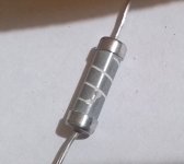
I put a picture with one of the resistor out of its ceramic shell.
in the same way. I meant at the end of the terminal , and not in the middle as should I expect. All of it was broked the same at the first end whilst resistance of the undamaged part shows close to its nominal value of 100 ohm. My question is why was blowed at the end and not in the middle please ?
I put a picture with one of the resistor out of its ceramic shell.
Attachments
Last edited:
The voltage would be highest at one end so the power dissipated would be greatest there.
Edit: Thinking about this some more, that's probably not the reason. The voltage drop should be consistent along its length. Maybe, less heat dissipation at the end?
Edit: Thinking about this some more, that's probably not the reason. The voltage drop should be consistent along its length. Maybe, less heat dissipation at the end?
Last edited:

Dielectric whistanding voltage no specified. The circuit was supplied at 400V. I don't talk about why the resistor broked up because is too evident. But why was broked at the end and not in the middle please?
Late: missed some posts, sorry.
Late: missed some posts, sorry.
Attachments

Yes, those rupture was the shot. Equally at low end cap for all 3 resistors, same type, same lot, used for test. The rest of the film was unaffected, showing from rupture to the other end almost its nominal resistance of ca.98ohm. So the resistors fused at one pretty end. Why not in the middle of the film ?
Last edited:
To my eyes, that rupture has occurred at a 'neck' location of the helical path, where the cross-sectional area of the path is smaller than elsewhere along the path. That may be by design or just a processing limitation during manufacture. I doubt it is 'by design', as that is somewhat related to how some fuse elements are constructed, with multiple notches in the current path to manage the ability of the fusing metal to control the arc that can occur.
What is the final voltage of the capacitor (here in the tubes section it could be several hundred volts)? Wait, I see in #5 it's 400V. That'll be (close to) the instantaneous voltage across the resistor (minus one or two volts for one or two diode drops). Calculate the current through the resistor with that voltage. Power resistors often have a surge current rating (which exceeds the power rating but only for a very short time so the resistor won't overheat), just for situations like this, but the circuit may be exceeding that rating. There would be a maximum voltage rating, possibly much higher than the voltage where it dissipates 5 watts, but you might be exceeding that too.
The data in post 5 doesn't tell these things, only the max change of resistance after the resistor is subjected to the max ratings, whatever they are.
The data in post 5 doesn't tell these things, only the max change of resistance after the resistor is subjected to the max ratings, whatever they are.
Just try and apply a 400V DC supply to a 100uF cap. If you use a supply that can supply Lots of current, you will get Lots of current.
The capacitor is a Dead Short at 0V (Start up with no charge in the cap).
There are things that limit the current, the transformer primary DCR, the transformer DCR. But if solid state diodes are used, they can supply many amperes of transient current.
400V/100 Ohm resistor is 4 Amps. Suppose the primary DCR reflects 100 Ohms to the secondary, and suppose the secondary DCR is 100 Ohms, then now we have 400V / (100R, + 100DCR + 100DCR) = 400V/300 Ohms = 1.33 Amps.
A typical B+ supply that is designed to provide 100mA to the output tubes of an amplifier . . .
If you have a capacitive input filter of a 100uF cap, the transient current might be as high as 1 Ampere (10 times the transient current versus the DC load current of the output tube).
Try passing 1 Ampere through some types of 5 Watt resistors.
All 5 Watt resistors are created equal, but some 5 Watt resistors are more equal than others.
Perhaps all the above might explain the broken resistor.
- Home
- Amplifiers
- Tubes / Valves
- Limiter surge resistor question