Re: maxon rules (atleast for me)
If low RPM is your recommendation, why not opt for a 300 RPM AC motor?dice45 said:
And as a high motor torque always improves sonics, i prefer the rare earth version of the maxon: enough torque at a managably low speed. Say 1200 for 33rpm.
Ray,
Interesting, makes sense, thank you.
@Vinyladdict
certainly an option. Just, 300rpm is too low for the maxon DC motor: the glide bearings will not suffer it over longer periods.
600 is minimum according to maxon and as i still want to have the option for 16rpm @platter, 1200 just do fine: excentricity 20Hz @33rpm.
rayfutrell said:In control systems design you select a gear ratio between the motor and driven load using the formula GR=SQRT(JL/JM) where GR is the gear ratio, JL is the load moment of inertia and JM is the motor moment of inertia. That way the transformed moment of inertia seen by the motor is the same as the motor moment of inertia. In other words, the gear ratio equalizes the inertias. This allows maximum acceleration of the load.
As an aside, the last control system I worked on was to drive 50 hp motors on a telemetry tracking antenna. Our power amplifier put out +-400 volts at 200 amperes. We had a 10kW dummy load for testing. You had to be real careful working on that amplifier.
Regards,
Ray
Interesting, makes sense, thank you.
@Vinyladdict
certainly an option. Just, 300rpm is too low for the maxon DC motor: the glide bearings will not suffer it over longer periods.
600 is minimum according to maxon and as i still want to have the option for 16rpm @platter, 1200 just do fine: excentricity 20Hz @33rpm.
Hi all.
very interesting threath. I’m using a Maxon (M040116) with glide bearings. When I ordered it, a engineer of Maxon warned me, better to use a motor with ball bearing for this low rpm (Pulley is 10mm in diameter). Nevertheless I bought it, mounted it one a linear sliding bearing (Igus DryLin N), to control the force of the belt extension and the lateral force on the bearing of the motor. After more than one year of (happily) using it, I can notice a small increase of the bearing clearence in the direction, the belt is pulling. Since I have no possibility to measure the force on the bearing, I screwed it most probably to high. Because then it sound best;-)
I will buy a Maxon with ball-bearing the next time, to look if there is an audible difference between this two bearings principles.
For speed-control I use a L200 Voltage-Regulator, which works very well (Circuit is to be seen in the L200 Apllication Note). This circuit acts a speed-regulator (for the pulley), since it measures the current through the motor and increases the voltage, when the motor is slowed down (Actually I dimensioned the values for a very slight regulation) When I first used a slippery belt the system (platter, belt, motor) began oscillating sometimes at heavy dynamics. So I took a non-slip belt and now I’m very glad with it. Next is to try the “standard” LT1085 (or was it 1083? I forgot…) circuit out.
BTW, Plinth is made of 50mm slate.
Regards, Boris
OK, we have progress, not much, but at least we are off the mark.
As this is a ultra low budget exercise I have been restricted to useing only materials that I have laying around the place so it aint going to be anything fancy. Oh, and although I am a toolmaker by training I now ply my living as a carpenter and woodworking tools are in the main unsuitable for working with metal, now thats a suprise isnt it?
I have the platter made. I cut down the Linn sub platter to remove the rim that the belt runs on. To keep the center of garavity low I removed the spindle and replaced it upside down. The platter is made from 6mm alloy plate that is screwed and glued to some 15mm MDF. I fixed it to the sub platter with some epoxy casting resin. To finish it of I glued some ruberised cork to the top and this has a .5mm recess in the midle for the record label.
I have enough 15mm MDF left to make a top plinth to mount the main bearing and tone arm. I plan to rout some of this away to reduce weight and to try and break up standing waves.
This will then sit on a heavy sub plinth that will house the motor. For this I have a bit of 40mm kitchen worktop.
I will try and post some pictures tommorow.
A bit more progress and some pictures.
The bottom plinth that will house the motor. Only the clearance hole for the bearing at the moment.
The top plinth with trirly bits!
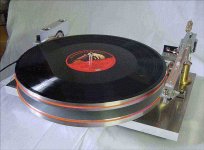
The platter. 15mm MDF, 6mm Alloy plate and cork. Its not visable in the photo but there is a .5mm recess for the record label.
The cut down Linn sub platter. I chain drilled and then used a jig saw, hence the pretty flower shape!
The underside of the top plate. Linn bearing is bolted to the ally plate then screwed to the plinth.
Total cost upto now, including the motor is £15.39!
Paul.
The bottom plinth that will house the motor. Only the clearance hole for the bearing at the moment.
An externally hosted image should be here but it was not working when we last tested it.
The top plinth with trirly bits!
An externally hosted image should be here but it was not working when we last tested it.
The platter. 15mm MDF, 6mm Alloy plate and cork. Its not visable in the photo but there is a .5mm recess for the record label.
An externally hosted image should be here but it was not working when we last tested it.
The cut down Linn sub platter. I chain drilled and then used a jig saw, hence the pretty flower shape!
An externally hosted image should be here but it was not working when we last tested it.
The underside of the top plate. Linn bearing is bolted to the ally plate then screwed to the plinth.
An externally hosted image should be here but it was not working when we last tested it.
Total cost upto now, including the motor is £15.39!
Paul.
Arcane helicopter technology filters down to audio
Anyone willing to try making one of these? It's another crazy 47 Labs product. Not much info on their site yet. Just a negative photo which I put through photoshop to see properly here. It has one belt doubled back over two stacked, counter-rotating platters. Any thoughts on the reasoning behind this? Maybe its plinth is so lightweight that it would suffer from torque reaction without this.
Max
Attachments
")
maybe you could type it in word and then paste it
So, what did you have to say?
Max
eeka chu said:You spend half an hour typing a long, detailed reply and then the forum kills it before you click post... I should keep a hammer beside me at the desk!
So, what did you have to say?
Max
GR=1
How about a simple GR=SQRT(JL/JM) implementation. Two identical DD TTs driven with GR=1 and a drive speed of 33 RPM.
Low drive speed is good, yes? Rotational intertial of load and motor are equal; just remember to put a record or anything else you will be using on the drive side too.
How about a simple GR=SQRT(JL/JM) implementation. Two identical DD TTs driven with GR=1 and a drive speed of 33 RPM.
Low drive speed is good, yes? Rotational intertial of load and motor are equal; just remember to put a record or anything else you will be using on the drive side too.
- Status
- This old topic is closed. If you want to reopen this topic, contact a moderator using the "Report Post" button.
- Home
- Source & Line
- Analogue Source
- Lightweight turntable plinth.