It's all explained here read it very carefully and all will be revealed even the white dot (important), by not telling you it will make you study the spec sheet.
http://www.diyaudio.com/forums/attachment.php?s=&postid=1541497&stamp=1213745766
Cheers George
http://www.diyaudio.com/forums/attachment.php?s=&postid=1541497&stamp=1213745766
Cheers George
explanation
Hi George,
Thanks for link ( I have already one on my computer ). I just get received explanation from Silonex Customer Service :
The last 'S' stands for "Sorted" so they sort the parts into ranges A, B, C, D......
The 307 and 387 on the other side of the parts are date codes.
307 is the 30th week of 2007.
387 is the 38th week of 2007.
CLS said:Are those 2 resistors of 150k (R1 & R2) there for reducing the current on the LDR's string, and making the voltage divisions by the VR string significant enough?
But, they also significantly reduce the voltage and current seen by the LDR's, wouldn't they?
So, the LDR's would never fully turned on, and there'd always be some degree of attenuation even if the VR is turned fully CW.
If I need this without the "buffer" stage, how can I modify the circuit?
The LDR resistance is sensitive to low diode current.
The values of the resistors were chosen for "best fit" (as judged by
me) for usable range and tracking off a single simple pot. You
certainly can run more or less current, you will just get a different
curve.
You can remove the buffer and use the attenuator as you please -
you will just tend to get more distortion with lower impedance loads.
Thanks for the kind reply, Mr. Pass")
I've been working on a 6-ch "Lightspeed Attenuator" these days. I have a really hard time playing with all those trim pots And, although I matched them previously, I found the actual matchings in the complete circuit are still less than ideal, especially I got 6ch to deal with.
Anyway, I'll update here when I get it done.
I've been working on a 6-ch "Lightspeed Attenuator" these days. I have a really hard time playing with all those trim pots
And, although I matched them previously, I found the actual matchings in the complete circuit are still less than ideal, especially I got 6ch to deal with.Anyway, I'll update here when I get it done.
This is my humble contribution to this thread:
6ch volume control:
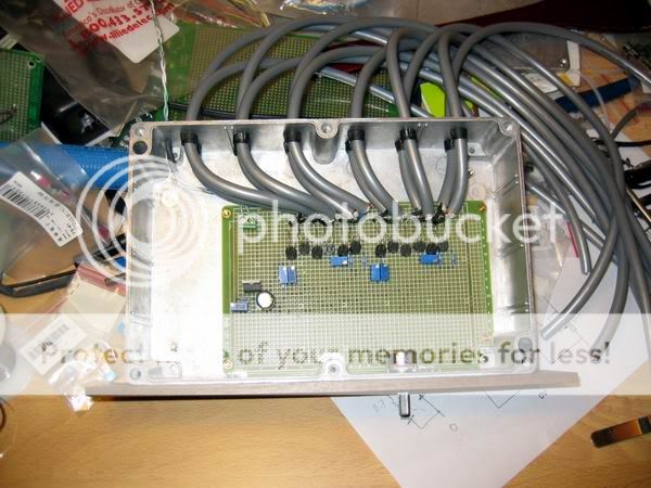
To make the "movable contacts" even less, I soldered all the cables on the board. Somewhat mess.
The front is better looking:

The back with all these 6ch I/O:
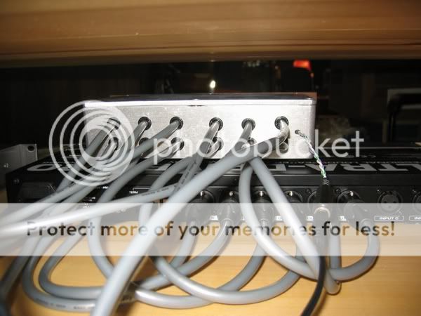
However, I have still not figured out the proper proportions of all those trim pots. Now I got the volume control only workable from 9 o'clock position and above. And before it reaches 12 o'clock, the SPL is ear-bleeding... The usable range is kind of small
6ch volume control:
To make the "movable contacts" even less, I soldered all the cables on the board. Somewhat mess.
The front is better looking:
The back with all these 6ch I/O:
However, I have still not figured out the proper proportions of all those trim pots. Now I got the volume control only workable from 9 o'clock position and above. And before it reaches 12 o'clock, the SPL is ear-bleeding... The usable range is kind of small
Lightspeed remote control
Hi Folks,
Long time no hear. Late last year I offered to provide a remote controlled voltage controlled current source module to drive a series resistor / shunt LDR volume control. I am sorry to say that I have been very busy since then with relocating my family and business to the Isle of South Uist in the Scottish Hebrides. We moved into a renovation project that was not finished and this is not high on my list of things to do again before I die. Anyway we are near enough back on track now and I have managed to find a little time to look at the volume control issue.
My original plan was to produce a series resistor / shunt LDR unit which is what I am using myself. There wasn’t much response to this idea at the time.
George suggested that I adapt it to drive the Lightspeed configuration and ensure it could be powered by a regulated 12 volt supply so it could be retrofitted to the lightspeed units that he makes. I set a test gig up last week in the workshop and it is behaving very nicely on the bench. I have been running the test gig for around 3 days in total and the volume level has not drifted from the original setting. The circuit is relatively simple and experienced DIY enthusiasts should have no problem adapting the circuit to suit their requirements. For those that do not feel comfortable with scratch build, provided enough interest is shown, I could be persuaded to have printed circuit boards manufactured or even provide built and tested modules. You will have to make yourself known if this is of interest or it will never happen.
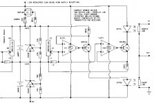
I used the Dallas DS1802 push button volume control in the original design (you were so close Tolu, but it can’t be used to directly control the LEDS as it’s current rating is too low) as the voltage controller for the voltage controlled current sources. This chip is easy to drive with a set of push buttons on the chassis and/or a multi-channel remote control transmitter and receiver (there are several kits available for these from various sources). The voltage reference stack is designed to keep the control voltage range within the common mode input range of most of the typical low cost FET input opamps readily available. A low noise device would be a good choice here. C3 and C4 can be selected for opamp stability. I used 100mf parts as these were to hand. C1 and C2 were required for reference device stability in this circuit layout. The ZR431 is the 2v5 100ma version of the 431 family. The 240R resistors (R8 and R9) allow a maximum led current of around 21 ma. It would not be a good idea to decrease the value of these resistors as you may exceed the rating of the LDR LED. You can increase the value of these resistors to shift the volume control operating range, if you so choose, to suit your listening requirements. It is also possible to adjust the volume control contour by mismatching these resistors or padding the Dallas wiper with resistors to the pot ends.
The nice thing about the DS1802 is that the chip allows 65 small volume increments and balance control is similarly fine. This should relax the matching requirements of the LDRs. If you find this is not fine enough, a high value trimmer pot can be placed across the LDR LEDs, as suggested in previous manual control designs, to allow further matching adjustment.
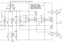
The circuit diagram shows one channel. Just copy it for the other channel. The voltage reference stack is common to both channels, as this should avoid possible dissimilar thermal drift problems if separate stacks were used.
If you want to use the series resistor / shunt LDR configuration replace the series LDR with a fixed resistor. You will have to choose the value of this resistor to suit your system requirements. You can also leave out IC1, C4, T3, OPTO1 and R9.
It is possible to get signal bleed through on switch-off so some form of auto mute circuit would be advisable or you could switch the power amps off before the volume control.
If anyone has any questions or can suggest any improvements feel free to discuss.
Regards
Paul Hynes
Hi Folks,
Long time no hear. Late last year I offered to provide a remote controlled voltage controlled current source module to drive a series resistor / shunt LDR volume control. I am sorry to say that I have been very busy since then with relocating my family and business to the Isle of South Uist in the Scottish Hebrides. We moved into a renovation project that was not finished and this is not high on my list of things to do again before I die. Anyway we are near enough back on track now and I have managed to find a little time to look at the volume control issue.
My original plan was to produce a series resistor / shunt LDR unit which is what I am using myself. There wasn’t much response to this idea at the time.
George suggested that I adapt it to drive the Lightspeed configuration and ensure it could be powered by a regulated 12 volt supply so it could be retrofitted to the lightspeed units that he makes. I set a test gig up last week in the workshop and it is behaving very nicely on the bench. I have been running the test gig for around 3 days in total and the volume level has not drifted from the original setting. The circuit is relatively simple and experienced DIY enthusiasts should have no problem adapting the circuit to suit their requirements. For those that do not feel comfortable with scratch build, provided enough interest is shown, I could be persuaded to have printed circuit boards manufactured or even provide built and tested modules. You will have to make yourself known if this is of interest or it will never happen.
I used the Dallas DS1802 push button volume control in the original design (you were so close Tolu, but it can’t be used to directly control the LEDS as it’s current rating is too low) as the voltage controller for the voltage controlled current sources. This chip is easy to drive with a set of push buttons on the chassis and/or a multi-channel remote control transmitter and receiver (there are several kits available for these from various sources). The voltage reference stack is designed to keep the control voltage range within the common mode input range of most of the typical low cost FET input opamps readily available. A low noise device would be a good choice here. C3 and C4 can be selected for opamp stability. I used 100mf parts as these were to hand. C1 and C2 were required for reference device stability in this circuit layout. The ZR431 is the 2v5 100ma version of the 431 family. The 240R resistors (R8 and R9) allow a maximum led current of around 21 ma. It would not be a good idea to decrease the value of these resistors as you may exceed the rating of the LDR LED. You can increase the value of these resistors to shift the volume control operating range, if you so choose, to suit your listening requirements. It is also possible to adjust the volume control contour by mismatching these resistors or padding the Dallas wiper with resistors to the pot ends.
The nice thing about the DS1802 is that the chip allows 65 small volume increments and balance control is similarly fine. This should relax the matching requirements of the LDRs. If you find this is not fine enough, a high value trimmer pot can be placed across the LDR LEDs, as suggested in previous manual control designs, to allow further matching adjustment.
The circuit diagram shows one channel. Just copy it for the other channel. The voltage reference stack is common to both channels, as this should avoid possible dissimilar thermal drift problems if separate stacks were used.
If you want to use the series resistor / shunt LDR configuration replace the series LDR with a fixed resistor. You will have to choose the value of this resistor to suit your system requirements. You can also leave out IC1, C4, T3, OPTO1 and R9.
It is possible to get signal bleed through on switch-off so some form of auto mute circuit would be advisable or you could switch the power amps off before the volume control.
If anyone has any questions or can suggest any improvements feel free to discuss.
Regards
Paul Hynes
Attachments
maximus said:Hi again folks,
Any tips on how to get attached drawings to be ledgible?
Regards
Paul Hynes
Hey Paul email a good one to me and I'll try.
georgehifi at optusnet.com.au
Cheers George
Save as high quality gif. It will still be small.
Save as .png, it is vector graphics and does not lose its quality with size.
Save as .pdf from nice original and add as attachment.
Post to a google web album and then add the hyperlink and we can all view it in original size.
Uriah
Save as .png, it is vector graphics and does not lose its quality with size.
Save as .pdf from nice original and add as attachment.
Post to a google web album and then add the hyperlink and we can all view it in original size.
Uriah
Lightspeed remote control circuit
Hi George,
I can just about read the detail in expand mode. Must be time to upgrade my computer (it's around 8 years old) or swap it for my daughter's computer while she is not around.
If anyone is having problems reading the drawing let me know and I will set up a PDF as suggested by Uriah.
Regards
Paul
Hi George,
I finally have my attenuator set-up for testing. I tried the latest version with one single pot with one trimmer, but I could hardly find the trimmer doing the job by adjusting the output level. I therefore went the way to the original design with double pots and 2 trimmers, but still I couldn't find the trimmer was functioning.
The control has been running for about 5 hours and I found the sound is a bit dull. I thought there must be something not working properly.
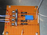
I have 5v supply with full wave rectifier 1n4005 to 1000uf and 0.1 ceramic, then to 7085, 200uf with 0.1 ceramic.
I also have 56uf with 0.1 ceramic for the LEDs- see picture for detail.
Both pair are tightly matched.
Thanks
Albert
I finally have my attenuator set-up for testing. I tried the latest version with one single pot with one trimmer, but I could hardly find the trimmer doing the job by adjusting the output level. I therefore went the way to the original design with double pots and 2 trimmers, but still I couldn't find the trimmer was functioning.
The control has been running for about 5 hours and I found the sound is a bit dull. I thought there must be something not working properly.
I have 5v supply with full wave rectifier 1n4005 to 1000uf and 0.1 ceramic, then to 7085, 200uf with 0.1 ceramic.
I also have 56uf with 0.1 ceramic for the LEDs- see picture for detail.
Both pair are tightly matched.
Thanks
Albert
Attachments
albertli said:....
I found the sound is a bit dull.....
Compared to ?
albertli said:Hi George,
I therefore went the way to the original design with double pots and 2 trimmers, but still I couldn't find the trimmer was functioning.
The control has been running for about 5 hours and I found the sound is a bit dull. I thought there must be something not working properly.
Thanks
Albert
I also went back to the dual pot, after trying a single, my single started to misbehave after a week of working fine, it started to go up and down in level by itself, all I could think it didn't like the dc current of all 4 leds running through it.
As for the your trimmer your circuit must be wrong if it does nothing.
As for it sounding dull, the only time I have heard this is when the CD player had a tube output stage which was over 2kohm output impedance.
And also another time when the interconnect from Lightspeed to power amp had too much capacitance, over 500pf and the input filter cap in the amp was over 200pf.
This combined capacitance of 700pf can give a high frequency roll off with the Lightspeed output resistance of 7kohms -3db @ 30khz or worse if there are more series resistances at the input of the power amp.
So without your trimmer working, this tells me something is not correct.
And a need to know your interconnect capacitance and the input circuit diagram of your amp would also be helpful.
Wait!!!! the Audio Note dac is tube output??? I think there lays your problem, it wouldn't drive fairy floss, what is the output impedance of this dac??
Cheers George
George,
Thanks for your ultra fast reply.
I've been keeping the control on over the night and tried some CDs this morning with or without the DAC. I hardly tell any different for the Cd's @200 ohms and my DAC @ 270 ohms. I therefore took the PSU down and have all those caps replaced by some good caps, 2000uf blackgate and a 470uf KZ blackgate then I put them back and turn on for about an hour. The music came after the tweak was completly identical, even my wife with wood ears could tell me that the sound is opening up. I can see some pictures now and hope it works better after the break in.
Eh......... I thought I better have those rectifier changed to UF4007 so they might also give a lift, who knows.
You mentioned about the total pf (700 the most ) for those interconnects. Can I just use my digital multi meter to test on those?
Albert
- Home
- Source & Line
- Analog Line Level
- Lightspeed Attenuator a new passive preamp