Very nicley thought out Paolo, even the loading problem of the source of the unused inputs has been addressed.
That's better than the DarTZeel NHB 18NS way of switching, should sound just like the single input Lightspeed Attenuator.
http://www.6moons.com/audioreviews/dartzeel2/preamp.html
But it's going to be expensive to make, were talking 14 led/ldr's packages for a switchable 3 input Lightspeed Attenuator plus all the other parts needed, not to mention the matching headache, that would tripple my sale price of $420us for the single input unit.
Cheers George
Attachments
Lightspeed Attenuator - thermal tracking
Hi George,
Perhaps you could reduce the "Tempco" of these touchy little fellas with something similar to the setup I used in my fet preamp, and then encapsulate it as per usual.
"The fets in my preamp were matched at a 40*C (a set temp) so when I built it, I mounted the fets on one side of a metal plate and a metal cased power resistor on the other and controlled the temp with a simple temp switch"
Quite possibly, it's not worth the trouble if there is to be an "auto compensating thingamejig" (!) to avoid all the effort with measuring and such, although I do like the simplicity of your design very much.
James
Hi James always good to see a fellow Aussie
James I don't find the thermal tracking a problem, once the units are matched they track thermally very well, unless you hit them with a blow torch or something.
It's just the matching of the resistance curve of each unit to the intensity of the led initially, once that is matched I have no problem with "Tempco"
When the Lightspeed is first powered up, granted there is a minute or so for it to stabilize thermally, but that only in the first minute of power up.
Cheers George
georgehifi said:Very nicley thought out Paolo, even the loading problem of the source of the unused inputs has been addressed.
glad you like it, George.

(BTW, let' give credit where it's due, I'm not the only one who is contributing to this design... as said, it's a group project).
But it's going to be expensive to make, were talking 14 led/ldr's packages for a switchable 3 input Lightspeed Attenuator plus all the other parts needed, not to mention the matching headache, that would tripple my sale price of $420us for the single input unit.
of course it's likely gonna be more expensive than a simple single input Lightspeed, but not too expensive after all... if you don't have to bother matching the led/ldr's and need to buy only the required ones.
")
Infact, one of the main ideas behind our project (already suggested here by others too) is to control the led/ldr's using a PIC with an auto-calibration system which automatically builds up a calibrated attenuation table for each channel/input.
In this way it is (should be) possible to obtain precise attenuation steps with virtually perfect channel matching as well as whatever input impedance is required/liked within a wide range (e.g. to suit the use as a standalone passive as well as input stage for an active preamp or an integrated amp) by simply acting on software... without any need for led/ldr matching.
Of course overall that's much more complicated than your nice minimalist solution but, since all the complication is kept completely out of the way of the audio signal, it's just as fine.
Since the required digital electronics is rather cheap, in the end it should not be too expensive and the extra features that it can provide (including full remote control) will be well worth it.
Moreover, the only hard part will be creating and optimizing the design... but once that's done, building it will be pretty easy and straightforward.

Lightspeed attenuator
At the risk of being electronically "stoned at the stake", I wonder if this marvellously colourless "pot" could be used to re-create good quality tone controls that we have all foregone because of the inherent distortion - I miss them a lot and have been looking foreward to the improvements in computer systems to alter the sound of some of the "less than perfect" recordings, but if a neat solution to "Baxandall", etc difficulties could use this device ..
__!__
!
! ... jh
(a new challenge, George!)
UnixMan said:
glad you like it, George.
Since the required digital electronics is rather cheap, in the end it should not be too expensive and the extra features that it can provide (including full remote control) will be well worth it.
Moreover, the only hard part will be creating and optimizing the design... but once that's done, building it will be pretty easy and straightforward.
Hi Paolo,
Would you be so kind as to post the final results here?
Thanks
John
Lots of lookers at the moment, please don't forget to vote.
I believe we need a PASSIVE PREAMP forum of our own, not to be stuck here in the solid state forum.
To get our own PASSIVE PREAMP forum you should vote here.
http://www.diyaudio.com/request/
Under the Passive Preamp Heading section that I've started with the first vote.
Cheers George
I believe we need a PASSIVE PREAMP forum of our own, not to be stuck here in the solid state forum.
To get our own PASSIVE PREAMP forum you should vote here.
http://www.diyaudio.com/request/
Under the Passive Preamp Heading section that I've started with the first vote.
Cheers George
Hi Paolo
"Though we were thinking about stereo, all the requirements and solutions (except for the number of channels) would be the same... if you (and/or perhaps someone else) is interested, it would be nice to merge our efforts."
That could be interesting, I will look at your project (although my Italian is zero) and get back in touch.
So far I have the contactless input circuit, the volume LDR control. DAC and micro (PIC) section schematics. The concept is that you can add channels from 2 to 6 (although more may be possible) as you wish and the micro sorts things out. The DACs are 16 bit which is a bit of a luxury but I believe lower resolution parts are pin compatibe.
I am a little busy at work at the moment (still there now) but will contact you later this week.
All the best
hey George,
I love reading this thread and building one of these is on my list of things to do.
I think you'd be better off pushing for a "Preamp" section first and see how that goes before going for a more restrictive "Passive preamp" section.
BTW: Passive to me means, resistors, no power, no active devices. So the Lightspeed does not count as a passive pre to my thinking. I do understand that you mean: passive equals no amplification.
regards
Greg Erskine said:hey George,
BTW: Passive to me means, resistors, no power, no active devices. So the Lightspeed does not count as a passive pre to my thinking. I do understand that you mean: passive equals no amplification.regards
Glad your enjoying it, and I hope you do build one, you won't regret it.
Passive v Active
Beg to differ there Greg, passive to me means no active components in the signal path, all we have in the Lightspeed is a passive resistor that can change it's value with different light source intensities, whether that be done with led's or sunshine or whatever, it's still a passive resistor.
I remember when PS Audio caused a big scene with their passive RIAA equalization circuit in their preamp, this was done by boosting the daylights out of the cartridge output then instead of the normal way of boosting the bass actively and cutting the highs for the RIAA stage, all they did was to leave the bass alone and severely passively cut the highs, no boosting involved at all in the RIAA, hence it being called a passive RIAA stage, this was also powered for source switching and active gain stages before and after the passive RIAA, but it was still called a passive RIAA even though there are active components all around.
If nothing were to be powered in the unit to be called passive then all those expensive Passive pre's out there that have remote volume or relay source switching couldn't be called passive either then.
And the Passive Pre-amp forum I'm trying to get votes for, are for all forms of Passives Pre-amps, Transformer based, Switched resistor, and all forms of resistive track based pots, as well as now LDR based.
Cheers George
Re: Hi Paolo
we're trying to make it as a group (team) project on an open forum, so there are no secrets... we'll be happy to share our results with you.
great! Of course I can translate all the relevant information for you, so don't worry about language.
I'm looking forward for your email...
jkeny said:
Would you be so kind as to post the final results here?
we're trying to make it as a group (team) project on an open forum, so there are no secrets... we'll be happy to share our results with you.
barryblue said:
That could be interesting, I will look at your project (although my Italian is zero) and get back in touch.
great! Of course I can translate all the relevant information for you, so don't worry about language.
I'm looking forward for your email...
see page 4 for the first draft of the audio circuit with contactless input switch.
e se anche noi provassimo a realizzare il selettore ingressi contactless!?
Si potrebbe fare come segue:
(N.B.: idea mia, NON ho la piu` pallida idea di come abbiano fatto nel prodotto commerciale di cui al link)
ci servono tre celle LDR per ingresso, connesse a "T".
Da una parte ci vanno i rispettivi ingressi, dall'altra sono unite tutte insieme. I rami "shunt" vanno a massa.
Sul canale attivo si usa la "L" formata dai primi due LED/LDR per settare l'attenuazione, mentre il terzo si puo` mettere "tutto aperto" oppure, meglio, lo si puo` sfruttare controllandolo in modo da mantenere costante l'impedenza di uscita. Bello!
(nel primo caso, visto che deve fare sostanzialmente da switch on/off, probabilmente converrebbe usare un Opto-FET piuttosto che un LED/LDR)
Sugli altri canali (inutilizzati) si lasciano invece "spenti" (max R) i due elementi serie e si "accende" l'elemento shunt, in modo da isolarli virtualmente dal circuito.
Per garantire una migliore separazione tra i canali, in parallelo ai rami "shunt" delle "T" si puo` anche mettere il contatto di un rele` per il muting. Questo ha anche il vantaggio di evitare di stressare inutilmente i LED/LDR, che NON gradiscono di essere tenuti accesi "full-blown" per lunghi periodi. Con il rele` chiuso i LED/LDR corrispondenti si possono tranquillamente lasciare "spenti" (o anche "accesi" ma con una corrente modesta che non crea problemi).
Da notare che la presenza dei rele` non cambia la natura "contactless" del sistema (e non dovrebbe influire minimamente del suono): ovviamente il canale in cui c'e` il contatto chiuso non e` attivo ed e` "isolato" dagli altri dalla resistenza max del LDR serie, che e` dell'ordine di svariati Mohm e piu`...
----------------------------------------------------------
UnixMan
This is Italian. Can U translate this for me UnixMan
The translator does a bad job.
Gajanan phadte
Here is a translation:
>e se anche noi provassimo a realizzare il selettore ingressi
>contactless!?
Why don't we try to design a contactless input selector?
>Si potrebbe fare come segue:
It could be done like this:
>(N.B.: idea mia, NON ho la piu` pallida idea di come abbiano >fatto nel prodotto commerciale di cui al link)
Note: this is a idea of mine, I don't know how commercial units are made
>ci servono tre celle LDR per ingresso, connesse a "T".
We need 3 LDR cells per input, arranged in a "T" connection
>Da una parte ci vanno i rispettivi ingressi, dall'altra sono unite >tutte insieme. I rami "shunt" vanno a massa.
On one side we have inputs, on the other side the cells are connected together. Shunt elements go to gnd.
>Sul canale attivo si usa la "L" formata dai primi due LED/LDR per >settare l'attenuazione, mentre il terzo si puo` mettere "tutto >aperto" oppure, meglio, lo si puo` sfruttare controllandolo in >modo da mantenere costante l'impedenza di uscita. Bello!
On the active channel the first series LDR and the shunt set the attenuation and the third is set to minimum resistance, or, better, controlled to keep impedance constant.
>(nel primo caso, visto che deve fare sostanzialmente da switch >on/off, probabilmente converrebbe usare un Opto-FET piuttosto >che un LED/LDR)
In the first case (third resistor at min resistance), since it is used like a switch, a Opto-fet might be used instead.
>Sugli altri canali (inutilizzati) si lasciano invece "spenti" (max R) i >due elementi serie e si "accende" l'elemento shunt, in modo da >isolarli virtualmente dal circuito.
The series LDR of the unused channels are left "off" and the shunt is kept "on" at min resistance.
>Per garantire una migliore separazione tra i canali, in parallelo ai >rami "shunt" delle "T" si puo` anche mettere il contatto di un >rele` per il muting. Questo ha anche il vantaggio di evitare di >stressare inutilmente i LED/LDR, che NON gradiscono di essere >tenuti accesi "full-blown" per lunghi periodi. Con il rele` chiuso i >LED/LDR corrispondenti si possono tranquillamente >lasciare "spenti" (o anche "accesi" ma con una corrente >modesta che non crea problemi).
To achieve a better channel separation the shunt element can be paralleled with a relay contact, closed in the "mute" situation.
This avoids to keep the leds constantly driven at their max current. They can be left "off" or on but with a lower current.
>Da notare che la presenza dei rele` non cambia la >natura "contactless" del sistema (e non dovrebbe influire >minimamente del suono): ovviamente il canale in cui c'e` il >contatto chiuso non e` attivo ed e` "isolato" dagli altri dalla >resistenza max del LDR serie, che e` dell'ordine di svariati Mohm >e piu`...
Please note that the relay doesn't change the contactless nature of the system, since the contacts are used in non-active channels and are isolated from the signal path by the high resistance of the second series resistor.
--------------
Note that the design has evolved from then: now the shunt element of the "T" network is just a relay contact used for channel muting, and a single LDR (per channel) is placed as common shunt element after the second series resistor.
This way we need less LDR and can control more easily the attenuation.
Also a clever use of the relay contacts allows to wire all the LEDs to the same current source, since the current return path is cut for the muted channels (and therefore leds are off).
Cheers
Andrea
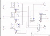
Here is the 2nd sketch (these nice drawings are courtesy of MarzioM).
Please note that this is a work in progress, and it have been already obsoleted by following discussion on the www.audiofaidate.it thread.
Most notably, the biggest difference -as anticipated by Andy- may be that (likely) the input LDRs (D1, D4, D6 in the diagram) will be operated as on/off "swithes" only and not also as part of the attenuator as shown.
This way they need not to be calibrated (except perhaps for a trimpot to make all channels "on" resistance equal) thus calibration system will not require any other special hardware and/or user actions on the inputs (*).
Again as anticipated by Andy, these LDRs may be possibly replaced by Opto-FETs (something like the H11F1), of course only if these will prove to be at least as "transparent" as the LDRs.
Now that I'm at it, there is also another option. They could even be simply replaced with fixed resistors (required to avoid shorting the outputs of sources connected to unselected/muted channel). Unfortunately, this otherwise interesting solution have some drawbacks, too.
BTW: does anybody know how these "Opto-FETs" (H11F1 and the like) are made and how do they work? Are they like a JFET with the (unconnected) gate exposed to a LED light or are they quite the same of an LED/LDR except for the semiconductor material used? or what???
Have anybody tried/heard of any "Opto-FETs" (such as the H11F1) used as an "audio switch" in any HiFi gear? What do you think about that?
---
Other open issue: the calibration system must still be discussed in more detail...
The option shown was intended to build tables of resistance vs. current for each LDRs separately (by varying the controlled CCS I1 current while keeping off all the other LED) and then use that data to build up the attenuation tables used to set the volume...
This is easy to do for what regard the hardware - as discussed in the italian forum, even simpler than the option shown: I1 can be a fixed CCS and the readout done by reading the voltage at the "output" line...), but implies much more complications in the software (and a bit slower calibration procedure).
A possible alternative is to provide a reference voltage on the input side and directly building the attenuation tables by measuring the resultant voltage at output. This may possibly require a bit more hardware (but maybe not so much) but seems much simpler to implement...
Other ideas?
note: (*)
if whatever follows the attenuator is / can be DC coupled, the output still needs to be disconnected (unplugged) during calibrations!
In principle, this could be avoided using yet another LDR or OptoFET "switch" in series with the output as well as another relay contact shunting it to gnd during calibrations... but running a calibration is needed only before system first use and -perhaps- may have to be repeated only after a really long while (to compensate for differences which may or may not appear due to LDR aging).
Given that we don't need to re-calibrate the system so often, requiring the user to unplug the outputs before running calibrations isn't such a big deal, and the extra circuit (which may also have a negative impact on the sound) isn't really required.
Attachments
My take on the calibration circuit: we have a common point for the LDRs that need matching, and this point is the output of the circuit. This can be both the source for calibration current and the measuring point of the resulting voltage on the LDR, provided ve keep the impedance of the ADC high enough (a simple buffer can do). - ** of course the calibration circuit is normally isolated from the audio path**
To calibrate the shunt element leave open the leds of the series elements and inject a suitable current into the shunt resistor (and adjust the corresponding led drive to achieve the desired voltage at the node).
Of course the uC outputs a voltage and the current is regulated via a voltage controlled current source like the one I posted on the italian forum (howland current pump).
To calibrate the series element leave open the led of the shunt (resistance won't be infinite but high enough. IMHO), close the mute contact of the element that needs calibration and repeat the calibration procedure.
Repeat this step for all the inputs.
There could be 2 calibration strategies:
1) variable current
Set "A" mA into the LDR, then raise the current until voltage stabilizes at say "B" volts
B/A will be the resistance in kOhms.
This is the most accurate, since allows to choose a suitable current to use the whole dynamic range of the ADC
2) fixed current
Depending on the ADC accuracy we can use a fixed CCS and measure the voltage across the resistor.
Less accurate in the low-ohm range but much simpler
What do you think about it?
Cheers
Andrea
Andypairo said:My take on the calibration circuit: we have a common point for the LDRs that need matching, and this point is the output of the circuit. This can be both the source for calibration current and the measuring point of the resulting voltage on the LDR, provided ve keep the impedance of the ADC high enough (a simple buffer can do). - ** of course the calibration circuit is normally isolated from the audio path**
[...]
What do you think about it?
This is basically the idea that we have discussed on audiofaidate and corresponds to the first option in my previous post.
One problem I see is the impedance of the current source. The LDRs can easily reach the Megaohm range, while typical real-world current sources are usually way far from that much.
As said, I'm also thinking about the (easier?) alternative of directly building the attenuation tables providing a (small, < 5V) reference voltage at the "T" junction on the input and directly measuring the resulting voltage at the output.
The hardware part can be implemented e.g. by switching the ground connection of the muting relay(s) from the control ground to a reference voltage source (of course while keeping the input LDRs or OptoFET "switches" off - I guess no source can be damaged by a small voltage connected to its output through the several Mohm of an "open" LDR or OptoFET...).
Not only this is simple to implement, but should also provide quite accurate attenuation tables in the whole dynamic range, and for whatever input impedance one wants to implement (within reasonable limits, of course...).
Note that, knowing the (fixed) reference voltage source, the input impedance can be obtained simply by measuring the current flowing through the voltage source - LDR attenuator circuit.
For what regards the software, it's simple... e.g., the first thing that came to my mind is:
1) set the desired input impedance by measuring it while (slowly!) rumping up the (same) current through both series and shunt LEDs
2) slowly adjust the DAC (controlling LEDs currents) until you reach the desired attenuation step and write the values to the table;
3) repeat point # 2 for all desired attenuation steps
4) repeat points # 1 to 3 for all inputs (different channels can be calibrated in parallel to save time).
done.
During operation, all you have to do in order to set any desired attenuation value is to look-up the table and set the DAC(s) accordingly.
Comments, ideas, suggestions?
- Home
- Source & Line
- Analog Line Level
- Lightspeed Attenuator a new passive preamp